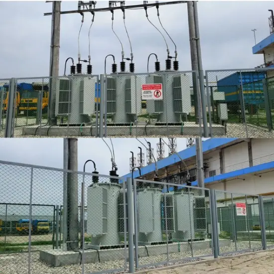
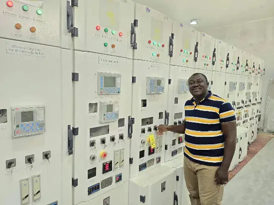
Replacement of 2x25MVA Power Transformers at an Old Substation in Madagascar
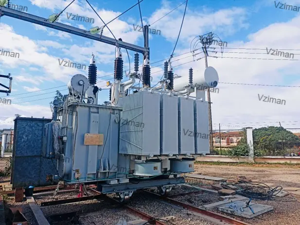
The on-site implementation took place at an old substation in a central city of Madagascar. The core tasks included the dismantling of old transformers, foundation renovation, unloading and installation of two 25MVA transformers, vacuum oil filling, and system commissioning. Vziman dispatched a team of technical experts to provide on-site guidance.
01 Project Overview
1.1Project Background
In April 2026, two RMR-25000/35 35kV power transformers were officially shipped and deployed for the Madagascar National Grid Upgrade Project. Manufactured by Vziman, these units serve as the core equipment replacement for an aging substation in a key central city. The equipment has now been successfully installed and commissioned, operating with stable performance.
Core Project Objectives:
This project is a typical retrofit initiative characterized by "replacing small capacity with large, and old units with new." The new transformers replaced two obsolete, high-energy-consuming 10MVA units that had been in service for over 20 years, aiming to resolve long-standing power supply bottlenecks in the region.
- Capacity Upgrade: The single-unit capacity was increased from 10MVA to 25MVA. This boosts the total power supply capability by 150%, thoroughly alleviating regional power shortages.
- Energy Efficiency Improvement: Utilizing new energy-saving materials, the project significantly reduces no-load and load losses, aligning with local green grid construction requirements.
1.2 Technical Parameters
|
No
|
Description
|
Unit
|
Guaranteed Data
|
|
1
|
Rated System Voltage
|
kV
|
35
|
|
2
|
Rated Frequency
|
Hz
|
50
|
|
3
|
Rated Capacity
|
MVA
|
2×25
|
|
4
|
Voltage Combination
|
kV
|
35±2×2.5%/10.5
|
|
5
|
Vector Group
|
Dyn11
|
|
6
|
Impedance Voltage
|
%
|
8.0
|
|
7
|
Ambient Temperature
|
℃
|
-5~+45 (Tropically Designed)
|
|
8
|
Altitude
|
m
|
1500 (Designed for High Altitude)
|
|
9
|
Noise Level
|
dB(A)
|
<65
|
02 Product Assembly
The manufacturing of the RMR-25000/35 power transformers strictly adheres to IEC 60076 and GB/T 6451 standards. The core process flow—"Core Stacking → Coil Winding → Active Part Assembly → Vacuum Oil Filling → Ex-works Testing"—ensures reliable insulation and stable operation. The specific procedures are as follows:
2.1 Core and Coil Manufacturing
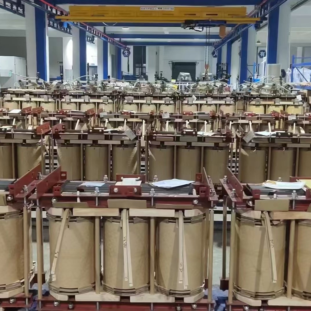
High-permeability cold-rolled silicon steel sheets are used for the fully mitered joint core stacking, which effectively reduces no-load losses. The high-voltage coils utilize a continuous structure, while the low-voltage coils adopt a double-helical structure, ensuring strong short-circuit resistance. After winding, the coils undergo constant-pressure drying treatment to remove moisture.
2.2 Active Part Assembly and Drying
The core, coils, and insulation components are assembled in a temperature-and-humidity-controlled cleanroom to form the active part (core and coil assembly). Subsequently, the entire assembly enters a large vacuum drying tank for vapor phase drying (using kerosene). This process thoroughly removes moisture from the insulation materials, guaranteeing superior insulation performance.
2.3 Vacuum Oil Filling and Sealing
The dried active part is moved into the oil tank. After connecting the oil circuits, vacuum oil filling is performed to ensure the oil is free of air bubbles. Following the oil filling, a sealing test is conducted, maintaining pressure for 24 hours to ensure zero leakage.
03 Inspection and Testing
- Routine Tests (RT): Include voltage ratio measurement, verification of vector group, measurement of short-circuit impedance and load loss, and measurement of no-load current and loss. These tests ensure that the data for every ex-works transformer exceeds national standards.
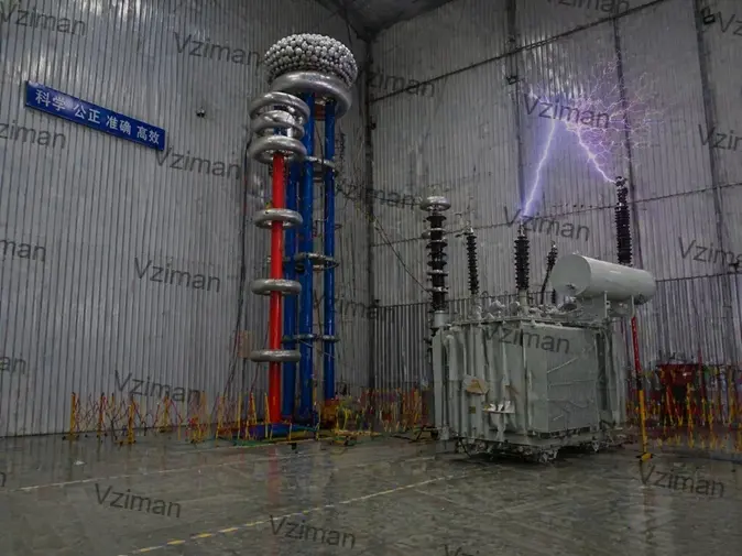
- Type Tests (TT): Temperature rise tests verify heat dissipation capability; lightning impulse tests verify insulation levels; sound level measurements verify noise reduction effectiveness.
- Special Tests (ST): Include zero-sequence impedance measurement, short-circuit withstand capability test (verified by calculation), and tank mechanical strength test (positive and negative pressure tests).
04 Packaging and Transportation
4.1 Packaging
- Main Unit Protection: We utilize fumigated wooden cases or steel-wood composite framed cases compliant with ISPM 15 standards, equipped with heavy-duty skids at the base. Critical components of the transformer body (such as bushings and conservators) are secured with foam positioning and reinforced with hard corner guards.
- Accessory Packaging: Fragile accessories like radiators and bushings are packed independently. The interior is filled with EPE pearl cotton and desiccants, while rust-preventive paper and humidity indicator cards are placed inside the crates.
4.2 Transportation
- Shipping Method: The equipment is transported via sea freight using containers or flat racks, shipping directly from Chinese ports to the Port of Toamasina in Madagascar. This ensures protection against moisture, salt spray, and vibration during the long-distance ocean voyage.
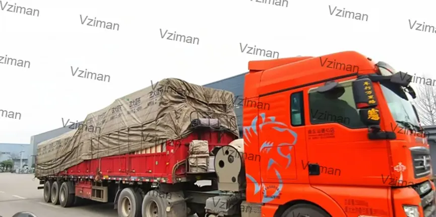
- Inland Transport: Considering the inland road conditions in Madagascar (where some sections are suboptimal), we employ heavy-duty low-bed trailers for inland transit. Routes are surveyed in advance to guarantee the safe arrival of the equipment at the substation site.
05 On-site Implementation and Conclusion
5.1 On-site Implementation
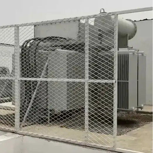
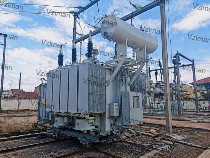
Prior to implementation, the team conducted a detailed re-survey of the existing substation foundations and formulated comprehensive plans for the power outage transition, as well as the oil draining and dismantling of the old transformers. Upon arrival of the equipment, a 200-ton mobile crane was utilized to remove the old units and position the new ones. During installation, strict control was maintained over the exposure time of the active part, followed by vacuum oil filling and hot oil circulation. Subsequently, cable connections for the 35kV and 10kV sides were completed, and protection relay settings were verified. After a successful 72-hour trial run—where temperature rise, noise levels, and voltage indicators all met requirements—the project passed acceptance inspection and was officially handed over.
06 Full Lifecycle O&M Managed Services
This service provides integrated, full-lifecycle management for power transformers. We cover every stage from procurement adaptation, manufacturing supervision, and packaging/transportation to installation, commissioning, routine maintenance, repairs, emergency response, and eventual decommissioning. With dedicated specialists managing specific projects and closed-loop control throughout the entire process, we ensure safe, stable operation and full traceability, completely eliminating your power supply concerns.
Drawings, Product Manuals, Selection Guides, Installation Instructions — [Get Materials]
Reference Standards:
|
IEC 60076-2:2011
|
Temperature Rise Limits: Specifies the limits for top oil temperature rise (≤60K) and average winding temperature rise (≤65K).
|
|
IEC 60076-3:2013
|
Insulation & Altitude Correction: Defines lightning impulse and power-frequency withstand voltage values, as well as insulation correction methods for high-altitude applications.
|
|
IEC 60076-5:2006
|
Short-Circuit Withstand: Stipulates the calculation and verification methods for thermal and dynamic stability under short-circuit currents.
|
|
IEC 60076-7:2018
|
Overload Capability: Provides guidance on the overload capacity of transformers under various ambient temperature conditions.
|
|
IEC 60076-10:2016
|
Noise Control: Prescribes noise measurement methods and limits (e.g., <65dB for 25MVA transformers).
|
|
SN/T 1179.1-2007
|
Import/Export Inspection: Sets out the basic requirements for the inspection of imported and exported power transformers.
|
|
IEC 60214-2
|
Tap Changers & Pressure Relief: Covers standards for tap changers and similar devices used in transformers, including requirements for pressure relief.
|
|
IEC 60076-18
|
Gas Relays (Buchholz): Specific standards for gas relays used in power transformers to detect internal faults.
|
|
IEC 60296
|
Insulating Oil Quality: Defines technical requirements for unused mineral insulating oils.
|
|
IEC 60076-2
|
Cooling System Design: Power transformer temperature rise standards that directly influence the design and selection of cooling systems.
|
Related News: https://qr.ae/pFhruN

 Login
Login