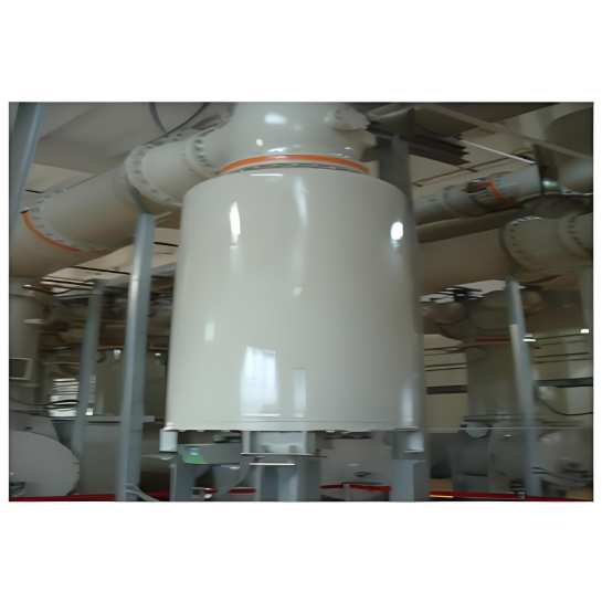
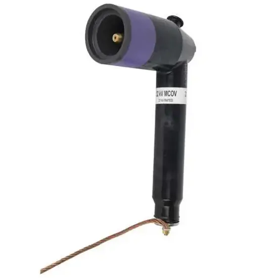
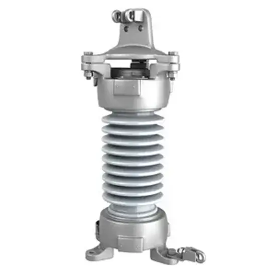
Tank-type Metal Oxide Surge Arresters for GIS
Key attributes
| Brand | ROCKWILL |
| Model NO. | Tank-type Metal Oxide Surge Arresters for GIS |
| Rated voltage | 200kV |
| Rated frequency | 50/60Hz |
| Series | Y10WF |
Product descriptions from the supplier
Description
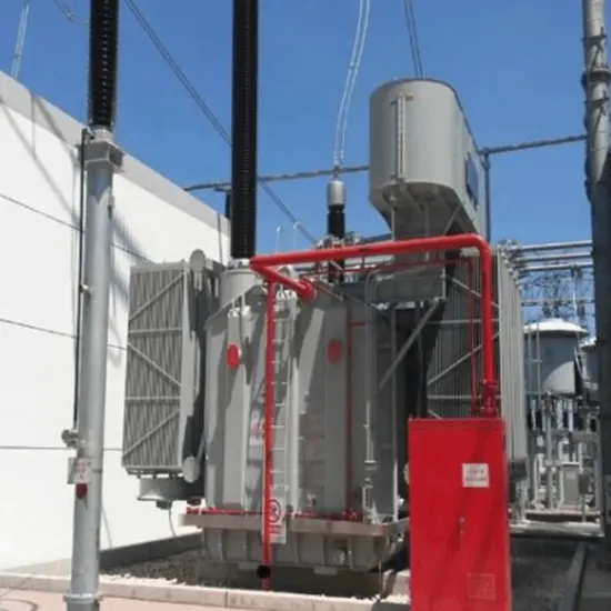
Tank-type Metal Oxide Surge Arresters for GIS are key protective devices specially designed for Gas Insulated Switchgear (GIS). They adopt a tank-type sealed structure and integrate high-performance Metal Oxide Varistors (MOV) internally, which can effectively suppress transient overvoltages caused by lightning, operating overvoltages, etc. in GIS systems. The arrester is directly installed inside GIS equipment. By quickly conducting surge currents to the ground terminal and clamping the voltage to a safe level, it protects core components in GIS such as circuit breakers, disconnectors, and busbars from overvoltage damage, ensures the stable and safe operation of the entire GIS system, and significantly reduces the risk of equipment failure and power outages.
Features
High Adaptability to GIS Systems: Specifically designed for GIS equipment, its size and interfaces perfectly match the GIS system, enabling seamless integration into compact GIS cabinets without occupying extra space, thus meeting the installation requirements of miniaturization and integration of GIS equipment.
Advantages of Tank-type Sealed Structure: Adopting a metal tank-type sealed design, it has extremely strong airtightness and mechanical strength, which can effectively isolate interference from dust, moisture, dirt, etc. in the external environment. It is suitable for various harsh environments such as high altitude, humidity, and heavy dust, ensuring the long-term stable operation of the arrester.
Excellent Overvoltage Suppression Capability: The built-in Metal Oxide Varistor (MOV) has excellent nonlinear volt-ampere characteristics. When an overvoltage occurs, it can respond quickly, rapidly absorb and release huge surge energy, and limit the overvoltage within the tolerance range of GIS equipment, with remarkable protection effect.
Low Energy Loss and Long Service Life: In normal operation, the MOV is in a high-resistance state, with extremely small leakage current and low energy loss, reducing unnecessary waste of electrical energy. At the same time, its material has high stability and strong anti-aging performance, with a long service life, reducing maintenance and replacement costs.
Safe and Reliable Operation Guarantee: It has good thermal stability and short-circuit resistance. When encountering extreme overvoltage or short-circuit faults, it can withstand short-term large current impacts without dangerous situations such as explosion, providing reliable guarantee for the safe operation of the GIS system.
Compliance with International Standards and Specifications: It is designed and manufactured in strict accordance with relevant international and domestic standards such as IEC and GB, and has passed a series of stringent electrical performance and environmental adaptability tests, ensuring that its performance indicators meet the high requirements of the GIS system and have wide applicability and interchangeability.
Model |
Arrester |
System |
Arrester Continuous Operation |
DC 1mA |
Switching Impulse |
Nominal Impulse |
Steep - Front Impulse |
2ms Square Wave |
Rated Voltage |
Nominal Voltage |
Operating Voltage |
Reference Voltage |
Voltage Residual (Switching Impulse) |
Voltage Residual (Nominal Impulse) |
Current Residual Voltage |
Current - Withstand Capacity |
|
kV |
kV |
kV |
kV |
kV |
kV |
kV |
A |
|
(RMS Value) |
(RMS Value) |
(RMS Value) |
Not Less Than |
Not Greater Than |
Not Greater Than |
Not Greater Than |
20 Times |
|
(Peak Value |
(Peak Value |
(Peak Value |
(Peak Value |
|||||
Y10WF1-90/232 |
90 |
66 |
72.5 |
130 |
198 |
232 |
266 |
600 |
Y10WF1-96/238 |
96 |
66 |
75 |
140 |
207 |
238 |
268 |
800 |
Y10WF1-100/260 |
100 |
110 |
78 |
145 |
221 |
260 |
291 |
600 |
Y10WF1-108/281 |
108 |
110 |
84 |
157 |
235 |
281 |
295 |
600 |
Y10WF1-100/260 |
100 |
110 |
73 |
145 |
221 |
260 |
291 |
800 |
Y10WF1-100/260 |
100 |
110 |
73 |
145 |
221 |
260 |
291 |
800 |
Y10WF1-100/260 |
100 |
110 |
78 |
145 |
221 |
260 |
291 |
600 |
Y10WF1-90/232 |
90 |
66 |
72.5 |
130 |
198 |
232 |
266 |
600 |
Y10WF1-96/238 |
96 |
66 |
75 |
140 |
207 |
238 |
268 |
600 |
Y10WF1-100/260 |
100 |
110 |
78 |
145 |
221 |
260 |
291 |
600 |
Y10WF1-108/281 |
108 |
110 |
84 |
157 |
235 |
281 |
295 |
600 |
Y10WF1-200/520 |
200 |
220 |
146 |
290 |
442 |
520 |
582 |
800 |
Y10WF1-200/520 |
200 |
220 |
146 |
290 |
442 |
520 |
582 |
800 |
Y10WF1-420/1046 |
420 |
550 |
318 |
565 |
858 |
1046 |
1137 |
2000 |
Y10WF1-444/1106 |
444 |
550 |
324 |
597 |
907 |
1106 |
1238 |
2000 |

Related Products
-
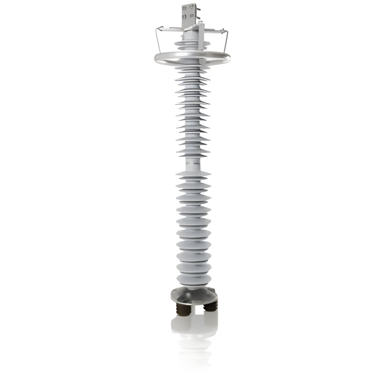
110 - 500kV Composite-Housed Line Surge Arresters
-
35 - 220kV Suspended Composite - Housed Metal Oxide Surge Arresters
-
500kV Series Porcelain-Housed Metal Oxide Surge Arresters
-
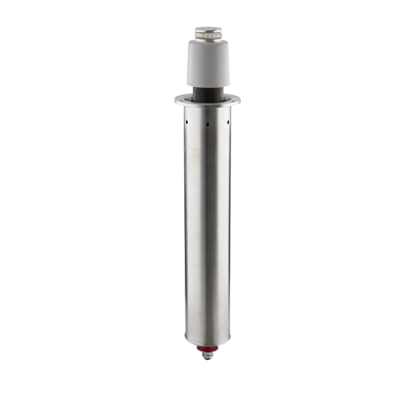
Underground Arresters
-
3 to 48kV Porcelain Housed Surge Arresters
-
3 to 550kV Station Class Metal-oxide surge arresters
-
30 to 52kV Outdoor Metal-oxide (MO) surge arrester
Related Knowledges
-
 Impact of DC Bias in Transformers at Renewable Energy Stations Near UHVDC Grounding ElectrodesImpact of DC Bias in Transformers at Renewable Energy Stations Near UHVDC Grounding ElectrodesWhen the grounding electrode of an Ultra-High-Voltage Direct Current (UHVDC) transmission system is located close to a renewable energy power station, the return current flowing through the earth can cause a rise in ground potential around the electrode area. This ground potential rise leads to a shift in the neutral-point potential of nearby power transformers, inducing DC bias (or DC offset) in their01/15/2026
 -
 HECI GCB for Generators – Fast SF6 Circuit Breaker1.Definition and Function1.1 Role of the Generator Circuit BreakerThe Generator Circuit Breaker (GCB) is a controllable disconnect point located between the generator and the step-up transformer, serving as an interface between the generator and the power grid. Its primary functions include isolating generator-side faults and enabling operational control during generator synchronization and grid connection. The operating principle of a GCB is not significantly different from that of a standard c01/06/2026
 -
 Distribution Equipment Transformer Testing, Inspection, and Maintenance1.Transformer Maintenance and Inspection Open the low-voltage (LV) circuit breaker of the transformer under maintenance, remove the control power fuse, and hang a “Do Not Close” warning sign on the switch handle. Open the high-voltage (HV) circuit breaker of the transformer under maintenance, close the grounding switch, fully discharge the transformer, lock the HV switchgear, and hang a “Do Not Close” warning sign on the switch handle. For dry-type transformer maintenance: first clean the porcel12/25/2025
 -
 How to Test Insulation Resistance of Distribution TransformersIn practical work, insulation resistance of distribution transformers is generally measured twice: the insulation resistance between thehigh-voltage (HV) windingand thelow-voltage (LV) winding plus the transformer tank, and the insulation resistance between theLV windingand theHV winding plus the transformer tank.If both measurements yield acceptable values, it indicates that the insulation among the HV winding, LV winding, and transformer tank is qualified. If either measurement fails, pairwise12/25/2025
 -
 Design Principles for Pole-Mounted Distribution TransformersDesign Principles for Pole-Mounted Distribution Transformers(1) Location and Layout PrinciplesPole-mounted transformer platforms should be located near the load center or close to critical loads, following the principle of “small capacity, multiple locations” to facilitate equipment replacement and maintenance. For residential power supply, three-phase transformers may be installed nearby based on current demand and future growth projections.(2) Capacity Selection for Three-Phase Pole-Mounted Tr12/25/2025
 -
 Transformer Noise Control Solutions for Different Installations1.Noise Mitigation for Ground-Level Independent Transformer RoomsMitigation Strategy:First, conduct a power-off inspection and maintenance of the transformer, including replacing aged insulating oil, checking and tightening all fasteners, and cleaning dust from the unit.Second, reinforce the transformer foundation or install vibration isolation devices—such as rubber pads or spring isolators—selected based on the severity of vibration.Finally, strengthen sound insulation at weak points of the ro12/25/2025
Related Solutions
-
 Intelligent Operation Solution for 12kV Vacuum Circuit Breakers: Integrating Real-time Monitoring & Lifetime OptimizationⅠ. Equipment Operation & MaintenanceIntelligent Monitoring System IntegrationMulti-parameter Real-time Monitoring: Embedded sensors (temperature, displacement, Hall effect current sensors) track contact temperature rise, mechanical characteristics (opening/closing speed, overtravel), coil current, and partial discharge signals. Data undergoes preprocessing via edge computing prior to cloud upload.Lifetime Prediction Model: Dynamically evaluates remaining lifespan using electrical wear data06/10/2025
 -
 SF6 Circuit Breaker Solutions for Outdoor Installation (Anti-Pollution & Seismic Resistance)I.Core Challenges in Outdoor InstallationIn high-voltage transmission and distribution systems, SF6 circuit breakers are exposed to complex outdoor environments for extended periods, facing the following critical issues:Pollution & Insulation DegradationDust, salt fog, and industrial pollutants in outdoor environments easily adhere to equipment surfaces. In coastal or industrial areas, pollution levels may reach Class IV, resulting in insufficient creepage distance and triggering flasho05/12/2025
 -
 12kV Indoor Vacuum Circuit Breaker Southeast Asia Solution: Anti-Corrosion Compact Design12kV Indoor Vacuum Circuit Breaker Southeast Asia Solution: Anti-Corrosion Compact DesignⅠ. Executive SummarySoutheast Asia faces rapidly growing electricity demand alongside environmental challenges including high temperatures, humidity, salt spray corrosion, and grid instability. This solution recommends Solid Insulated Pole-Mounted Vacuum Circuit Breakers (VCB) featuring high reliability, compact design, and smart monitoring. Tailored for tropical climates and industrial scenarios, it06/10/2025


