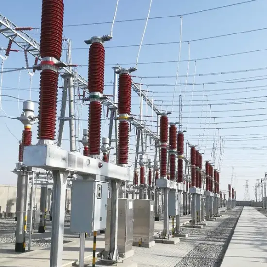
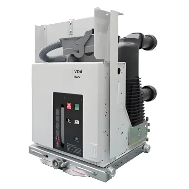
• 110 - 500kV Composite-Housed Line Surge Arresters
110 - 500kV Composite-Housed Line Surge Arresters
discuss personally
Model
YH10CX1-288/755
Basic info
Brand ROCKWILL
Model NO. 110 - 500kV Composite-Housed Line Surge Arresters
Rated voltage 220kV
Rated frequency 50/60Hz
Series YH10CX
Product Detail

Description

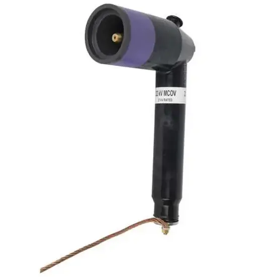
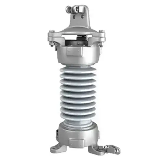
110 - 500kV Composite-Housed Line Surge Arresters are specialized protective devices designed for high-voltage transmission lines operating within the 110kV to 500kV range. Encased in durable composite housings (typically silicone rubber), they integrate advanced metal oxide varistor (MOV) technology. Installed directly on transmission lines, these arresters serve as a critical defense against overvoltages caused by lightning strikes, switching transients, and other electrical disturbances. By rapidly diverting surge currents to the ground and clamping voltage levels to safe thresholds, they prevent damage to line components, minimize power outages, and ensure the stable and efficient operation of 110 - 500kV transmission networks.

Features

Broad Voltage CompatibilityTailored to cover the 110kV to 500kV range, these arresters are engineered to match the specific voltage requirements of high-voltage transmission lines. This versatility allows them to provide consistent and reliable protection across various segments of the power grid within this voltage spectrum.

Durable Composite HousingThe composite (silicone rubber) housing offers exceptional performance. It exhibits strong resistance to environmental factors such as UV radiation, extreme temperatures, moisture, and pollution, ensuring long-term stability even in harsh outdoor conditions. Additionally, its lightweight nature simplifies installation and reduces the load on transmission line structures.

High-Performance MOVsEquipped with high-quality metal oxide varistors, these arresters feature excellent nonlinear resistance characteristics. During overvoltage events, the MOVs quickly conduct large surge currents, effectively limiting voltage spikes. In normal operation, they maintain a high-resistance state, minimizing leakage current and energy loss.

Line-Specific DesignDesigned specifically for integration with transmission lines, they have a compact and streamlined structure that fits seamlessly into line configurations. This design ensures minimal impact on line performance while providing optimal protection, making them suitable for both overhead and certain underground transmission line setups.

Superior Surge HandlingCapable of withstanding high impulse currents generated by severe lightning strikes and switching surges. Their robust surge handling capacity ensures that even under extreme electrical disturbances, the arresters can effectively mitigate the impact, safeguarding line insulators, conductors, and other critical components.

Low Maintenance RequirementsThe composite housing is resistant to aging and corrosion, reducing the need for frequent maintenance. The MOVs are designed for long-term reliability, with stable performance over extended periods, minimizing downtime and operational costs associated with upkeep.

Compliance with StandardsAdheres to international industry standards such as IEC 60099 - 4 and ANSI/IEEE C62.11, ensuring compatibility with global transmission systems. Compliance with these standards guarantees that the arresters meet strict safety and performance criteria, providing confidence in their operational effectiveness.

Enhanced Grid Reliability:By preventing line tripping and equipment damage caused by overvoltages, these arresters contribute significantly to the overall reliability of the power grid. They help maintain continuous power transmission, reducing the frequency and duration of outages, which is crucial for meeting the demands of industrial, commercial, and residential users.

Model 

Arrester

System

Arrester Continuous Operation

DC 1mA

Switching Impulse

Nominal Impulse

Steep - Front Impulse

2ms Square Wave

Nominal

Rated Voltage

Nominal Voltage

Operating Voltage

Reference Voltage

Voltage Residual (Switching Impulse)

Voltage Residual (Nominal Impulse)

Current Residual Voltage

Current - Withstand Capacity

Creepage Distance

kV

kV

kV

kV

kV

kV

kV

A

mm

(RMS Value)

(RMS Value)

(RMS Value)

Not Less Than

Not Greater Than

Not Greater Than

Not Greater Than

20 Times


(Peak Value

(Peak Value

(Peak Value

(Peak Value


YH10CX1-102/296

102

110

81.6

148


296


600

5438

YH10CX1-204/592

204

220

159

296


592


600

10600

YH20CX1-396/1050

396

500

297

561


1050


1200

23310

YH10CX1-204/592K

204

220

159

296


592


600

5400

YH10CX1-288/755

220

330

216

408


755


600

16100

Know your supplier
ROCKWILL
Rockwill Electric Group Global Manufacturer of High voltage and medium-voltage power equipment and smart grid solutions. Headquartered in Wenzhou, China. Serving 100+ countries with quality, innovation, and trust. What We Offer: • HV-MV switchgear (VCB, SF₆ circuit breakers, RMU, GIS) • Distribution transformers and substations • Smart grid and monitoring systems • Solar, wind, EV charging, and energy storage solutions • EPC turnkey power projects Certified: ISO 9001 / ISO 14001 / ISO 45001
Main Categories
High Voltage Electrical Apparatus
Business Type
Design/Manufacture/Sales
Highest Annual Export (USD)
$150,000,000
Professional Experience
16 years
Workplace
108000m²m²
占位
占位
Related Products
Related Knowledges
What is the difference between a dielectric and an insulator?
Dielectrics and insulators are distinguished primarily by their applications. One of the main differences is that a dielectric can store electrical energy by becoming polarized in an electric field, whereas an insulator resists the flow of electrons to prevent current conduction. Other key differences between them are outlined in the comparison chart below.Definition of DielectricA dielectric material is a type of insulator that contains few or no free electrons. When subjected to an electric fi
Edwiin
08/30/2025
Fault Analysis and Treatment of Oil-Immersed Transformers
Oil Leakage at Welded JointsOil leakage at welded joints primarily stems from poor welding quality, such as incomplete or detached welds, and defects like pinholes and gas pores. Although oil-immersed transformers are initially coated with solder and paint during manufacturing, potentially masking these issues temporarily, the defects tend to surface during operation. Additionally, electromagnetic vibration can cause weld cracks, leading to oil leakage.To resolve such leaks, the first critical s
Edwiin
08/29/2025
What losses occur during operation of the transformer? How to reduce losses?
Transformers experience various types of losses during operation, primarily categorized into two main types: copper losses and iron losses.Copper LossesCopper losses, also known as I²R losses, are caused by the electrical resistance of the transformer windings—typically made of copper. As current flows through the windings, energy is dissipated in the form of heat. These losses are proportional to the square of the load current (I²R), meaning they increase significantly with high
Rockwell
08/29/2025
Cable Fault Detection, Testing, Location and Repair
I. Methods for Cable Testing and Inspection:Insulation Resistance Test: Use an insulation resistance tester to measure the insulation resistance value of the cable. A high insulation resistance value indicates good insulation, while a low value may suggest insulation problems requiring further investigation.Voltage Withstand Test: Apply a high-voltage test using a high-voltage tester to verify whether the cable can withstand high voltage under its rated operating conditions. Under normal circums
Leon
08/29/2025
Cable Quality Inspection and Cable Detection & Testing
Power cable quality inspection and cable testing are conducted to ensure that the cable's quality and performance meet specified requirements, thereby guaranteeing the safe and stable operation of power systems. Below are some common contents of power cable quality inspection and cable testing:Visual Inspection: Check the cable surface for physical defects such as damage, deformation, or scratches to ensure the cable's exterior is intact.Dimensional Measurement: Measure dimensional parameters su
Edwiin
08/29/2025
Transformer Detection, Testing, Maintenance and Servicing
Transformer testing, inspection, and maintenance are essential tasks to ensure normal operation and extend the service life of transformers. Below are some recommended steps:Visual Inspection: Regularly inspect the transformer's exterior, including the enclosure, cooling system, and oil tank. Ensure the enclosure is intact, free from corrosion, damage, or leakage.Insulation Resistance Testing: Use an insulation resistance tester to check the transformer's insulation system. Verify that the insul
Vziman
08/29/2025
×
Inquiry
Download
IEE-Business is dedicated to serving the personnel in the global power industry.
Join IEE-Business, not only can you discover power equipment and power knowledge, but also canhnd like - minded friends!