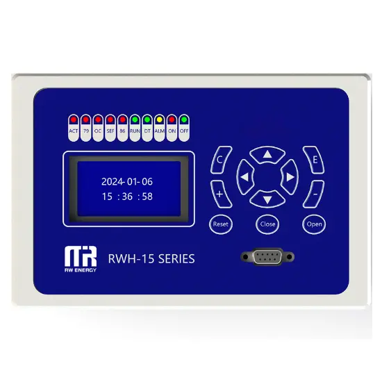
Overhead Line Protection Switch Intelligent Controller


Key attributes
| Brand | RW Energy |
| Model NO. | Overhead Line Protection Switch Intelligent Controller |
| Rated voltage | 230V ±20% |
| Rated frequency | 50/60Hz |
| Electric energy consumption | ≤5W |
| Series | RWK-LC |
Product descriptions from the supplier
Description
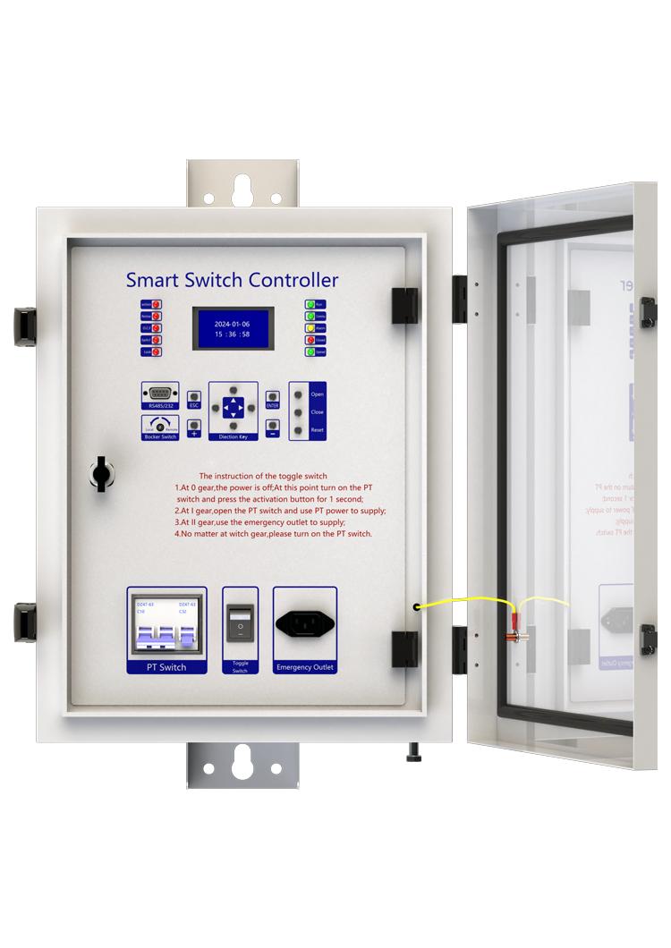
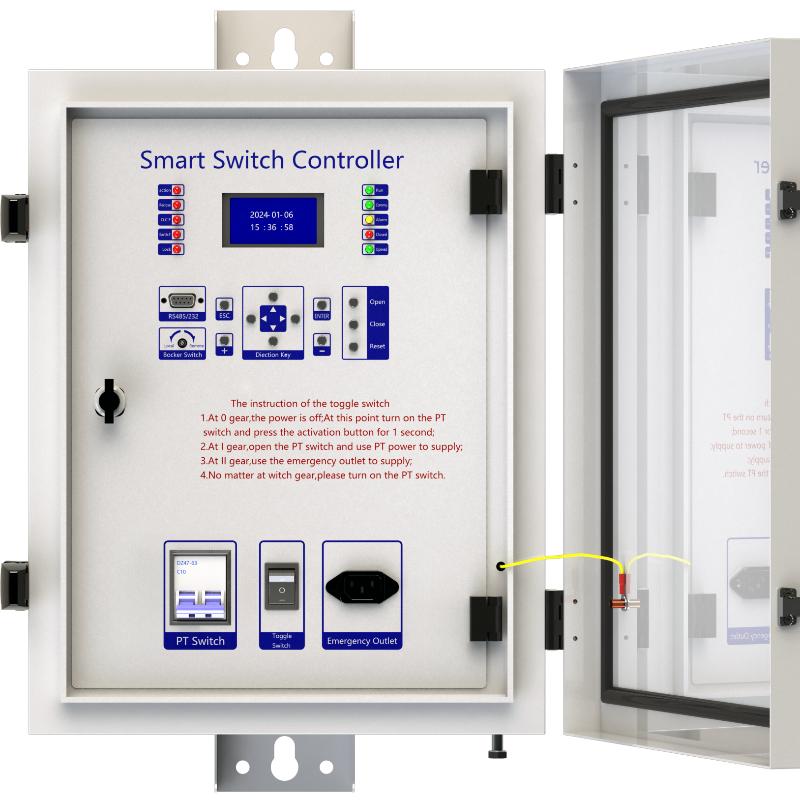
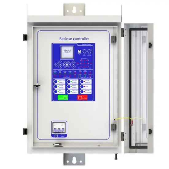
RWK-LC overhead line protection switch intelligent controller is medium voltage overhead line grid monitoring unit, it can be equipped with RCW(RVB) type vacuum circuit breaker for achieve of automatic monitoring, fault analysis and event records.
Its given to us a safety power grid for cutting line fault and automatic recovery operation and power automation.
RWK-LC series is suitable for up to 35kV outdoor switchgear using, include: vacuum circuit breakers, oil circuit breakers and gas circuit breakers. RWK-LC intelligent controller is gathering with line protection, control, measurement and monitoring of voltage and current signals integrated automation and control devices outdoors.
RWK is an automatic management unit for single way/multi ways/ring network/two power sourcing, provided with all voltage and current signals and all functions. RWK-LC column switch intelligent controller supports: Wireless (GSM/GPRS/CDMA), Ethernet mode, WIFI, optical fiber, power line carrier, RS232/485, RJ45 and other forms of communication, and can access other station premises equipment (such as TTU, FTU, DTU, etc.).
Main function introduction
1. Protection relay functions:
1) 49 Thermal Overload,
2) 50 Three-section of Overcurrent (Ph.OC) ,
3) 50G/N/SEF Sensitive Earth Fault (SEF),
4) 27/59 Under/Over Voltage (Ph.OV/Ph.UV),
5) 51C Cold load pickup (Cold load).
2. Supervision functions:
1) 60CTS CT Supervision,
2) 60VTS VT Supervision,
3. Control functions:
1) 86 Lockout,
2) 79 Auto reclose,.
3) circuit-breaker control,
4. Monitoring Functions:
1) Primary currents for Phases and Zero sequence current,
2) Primary PT Voltage,
3) Frequency,
4) Binary Input/Output status,
5) Trip circuit healthy/failure,
6) Time and date,
7) Fault records,
8) Event records.
5. Data Storage functions:
1) Event Records,
2) Fault Records,
3) Measurands.
Technology parameters

Device structure


About customization
The following optional functions are available: Power supply rated at 110V/60Hz , Upgrade SMS Function. Upgrade RS485/RS232 Communication interface Function
For detailed customization, please contact the salesman.
Q: What does the line protection switch controller do?
A: It is mainly used to protect the line security. When the line is overloaded, short circuit and other abnormal conditions, the line protection switch controller can quickly detect these problems, and then automatically cut off the circuit, to prevent the line from being damaged by too much current, to avoid causing fire and other dangerous situations. Q: How does it detect a line anomaly?
A: It has a sophisticated current detection device inside. When the current in the line exceeds the set safe value, whether it is due to overload caused by too many appliances or short circuit caused by line fault, the detection device can sense the change in the current and trigger the controller action.
Q: Is the line protection switch controller durable?
A: Generally speaking, if it is a qualified product, it is more durable. The electronic components used are strictly screened, and the housing has good protection and can adapt to different environmental conditions, but it is also checked and maintained regularly to ensure that it works properly.

By increasing the magnification of SEF sampling, we update the program to ensure its sampling accuracy meets the requirements within the range of 0.8-1 amps.
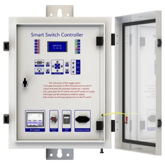
NOTE: In the "GSM" menu, it need be set the first phone number, and the limit of the phone number(ADMIN/USER/OFF)①.The default phone number is 13 bits, For example+86 1385758963,if the number is less than 13 bits, the remaining number of digits are replaced by A.
STEP1: config on the Controller
- Set the number in the controller, press [ENTER] key to "EDIT" menu;
- Press [ENTER] key and then press [→] key to "GSM" menu;
- Press [ENTER] key to set the number and limit, first you need to change the number to 8613857589636 (please ignore the symbol "+", and the remaining number of digits are replaced by A ), then change the limit to "Admin", After this, press [ENTER] key and entry password "0099" to save.
STEP2:Operation on the Phone
- Open the APP, the password is admin123 (the users can change the password in the APP );
- When enter the APP, click "Add" to set the value of the controller;
- Then click "Submit" to save;
- Find "Line1" and click "Operate" to operate the device;
- Click "Refresh" and wait for the update message;
- Find "Power" menu, click "Refresh" and wait for the update message.
Three-Section Overcurrent Protection is a coordinated protection scheme widely used in power systems to detect and isolate faults (e.g., short circuits) while ensuring selective tripping. It consists of three stages with distinct operating characteristics based on current magnitude and time delay:
- Instantaneous Overcurrent Protection (Section I)
Function: Responds immediately to severe overcurrents exceeding a high-set threshold (e.g., 5–10 times the rated current).
Purpose: Rapidly clears close-in faults (near the protection device) to prevent equipment damage.
Key Feature: No intentional time delay (operates in milliseconds).
- Time-Delayed Overcurrent Protection (Section II)
Function: Triggers after a predefined short delay (e.g., 0.1–0.5 seconds) for moderate overcurrents (e.g., 2–5 times the rated current).
Purpose: Handles faults farther from the protection device, allowing downstream breakers to clear localized faults first (selectivity).
Coordination: Employs a time-graded scheme—higher fault currents (closer faults) trip faster, while lower currents (remote faults) trip slower.
- Backup Overcurrent Protection (Section III)
Function: Activates after a longer time delay (e.g., several seconds) for low-magnitude overcurrents (e.g., 1.2–2 times the rated current).
Purpose: Serves as a backup for primary protection (Sections I/II) and addresses overloads or persistent faults.
Characteristic: May use an inverse-time curve (trip time decreases as current increases).
Coordination Principle
The three sections work hierarchically:
Section I clears severe faults instantly.
Section II handles moderate faults with short delays, prioritizing system selectivity.
Section III provides backup protection, ensuring reliability if upstream protections fail.
This layered approach minimizes outage scope, balances speed and selectivity, and enhances grid stability.

Related Products
-
General Protection Device
-
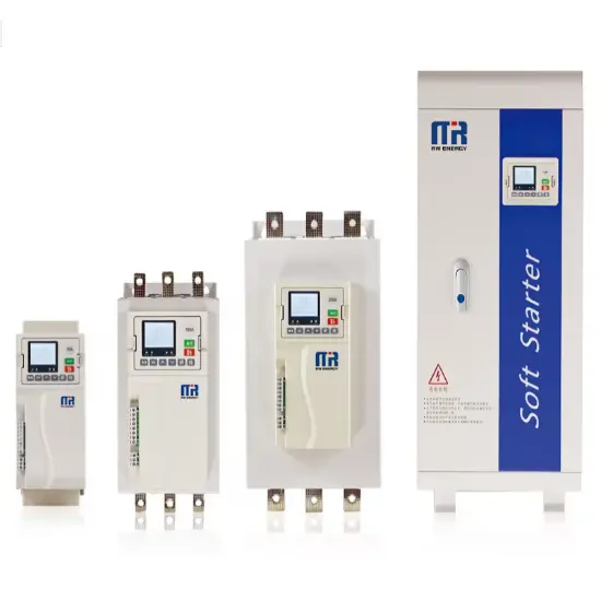
RWS-7000 Built - in bypass type motor soft starter
-
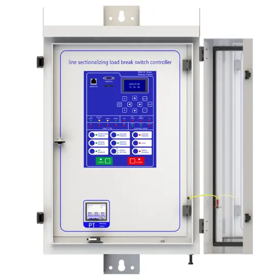
Line Sectionalizing Load Break Switch Controller
-
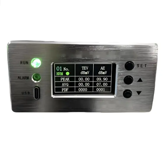
RWJS Partial Discharge Online Monitoring System for Ring Main Units
-
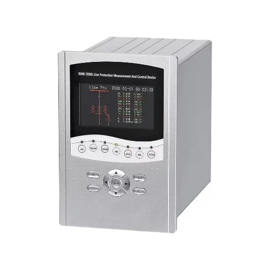
RWB-7000L Line Protection Measurement And Control Device
-
Feeder Terminal Unit
-
Advanced Recloser Controller
Related Knowledges
-
 Faults and Handling of Single-phase Grounding in 10kV Distribution LinesCharacteristics and Detection Devices for Single-Phase Ground Faults1. Characteristics of Single-Phase Ground FaultsCentral Alarm Signals:The warning bell rings, and the indicator lamp labeled “Ground Fault on [X] kV Bus Section [Y]” illuminates. In systems with a Petersen coil (arc suppression coil) grounding the neutral point, the “Petersen Coil Operated” indicator also lights up.Insulation Monitoring Voltmeter Indications:The voltage of the faulted phase decreases (in01/30/2026
 -
 Neutral point grounding operation mode for 110kV~220kV power grid transformersThe arrangement of neutral point grounding operation modes for 110kV~220kV power grid transformers shall meet the insulation withstand requirements of transformer neutral points, and shall also strive to keep the zero-sequence impedance of substations basically unchanged, while ensuring that the zero-sequence comprehensive impedance at any short-circuit point in the system does not exceed three times the positive-sequence comprehensive impedance.For 220kV and 110kV transformers in new constructi01/29/2026
 -
 Why Do Substations Use Stones, Gravel, Pebbles, and Crushed Rock?Why Do Substations Use Stones, Gravel, Pebbles, and Crushed Rock?In substations, equipment such as power and distribution transformers, transmission lines, voltage transformers, current transformers, and disconnect switches all require grounding. Beyond grounding, we will now explore in depth why gravel and crushed stone are commonly used in substations. Though they appear ordinary, these stones play a critical safety and functional role.In substation grounding design—especially when multiple gr01/29/2026
 -
 Why Must a Transformer Core Be Grounded at Only One Point? Isn't Multi-Point Grounding More Reliable?Why Does the Transformer Core Need to Be Grounded?During operation, the transformer core, along with the metal structures, parts, and components that fix the core and windings, are all situated in a strong electric field. Under the influence of this electric field, they acquire a relatively high potential with respect to ground. If the core is not grounded, a potential difference will exist between the core and the grounded clamping structures and tank, which may lead to intermittent discharge.I01/29/2026
 -
 Understanding Transformer Neutral GroundingI. What is a Neutral Point?In transformers and generators, the neutral point is a specific point in the winding where the absolute voltage between this point and each external terminal is equal. In the diagram below, pointOrepresents the neutral point.II. Why Does the Neutral Point Need Grounding?The electrical connection method between the neutral point and earth in a three-phase AC power system is called theneutral grounding method. This grounding method directly affects:The safety, reliabilit01/29/2026
 -
 What’s the Difference Between Rectifier Transformers and Power Transformers?What is a Rectifier Transformer?"Power conversion" is a general term encompassing rectification, inversion, and frequency conversion, with rectification being the most widely used among them. Rectifier equipment converts input AC power into DC output through rectification and filtering. A rectifier transformer serves as the power supply transformer for such rectifier equipment. In industrial applications, most DC power supplies are obtained by combining a rectifier transformer with rectifier equ01/29/2026
Related Solutions
-
 Distribution automation systems solutionsWhat are the difficulties in overhead line operation and maintenance?Difficulty one:Overhead lines of distribution network have wide coverage,complicatedterrain,many radiation branches and distributed power supply,resultingin "many line faults and difficulty in fault troubleshooting".Difficulty Two:Manual troubleshooting is time-consuming and laborious.Meanwhile,therunning current,voltage and switching state of the line cannot be graspedin real time,because of the lack of intelligent technical m04/22/2025
 -
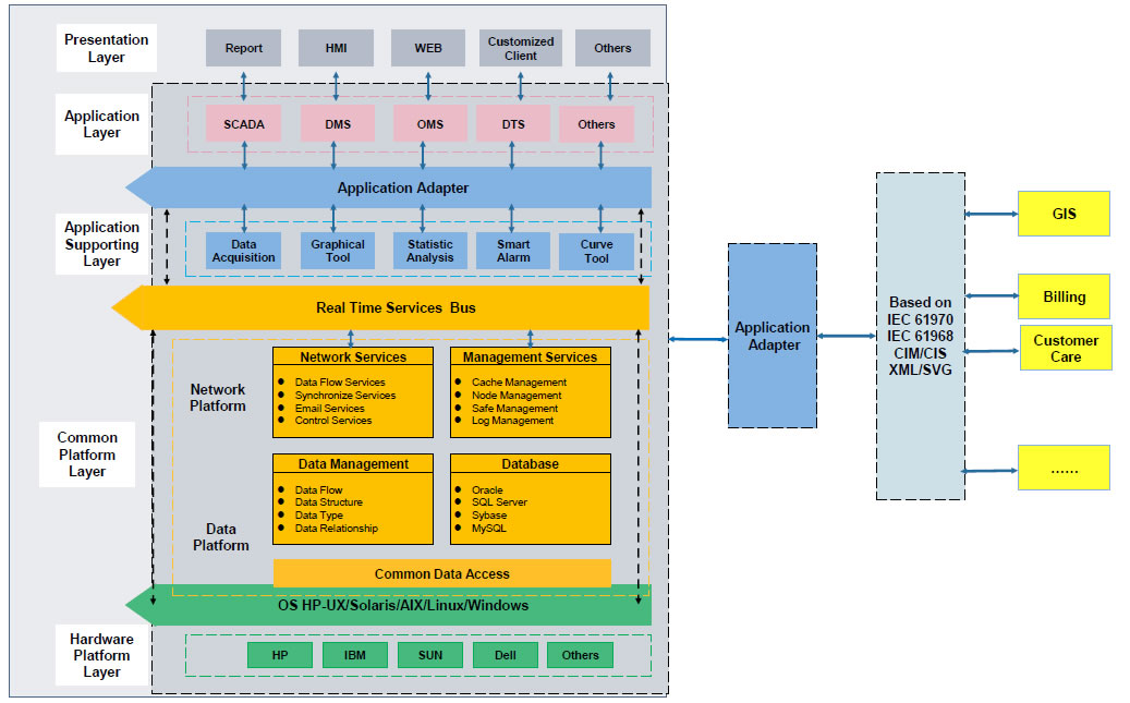 RW8000 DMS Distribution Management System SolutionsOverviewNowadays, the development trend of power grid is intellectualization. As an important part of power grid, the power distribution system is very close to the customers and it has to run properly. The distribution management system (DMS)played an important role in it.Introduction:RW8000 power distribution management system (DMS) is designed for the smart grids. It is based on real-time application, centered on distribution network operation and management, focusing on the business process09/07/2023
 -
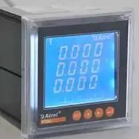 High-Precision Electrical Parameter Monitoring System Solution1.IntroductionWith the increasingly stringent requirements for power supply quality in high-end facilities such as precision manufacturing, medical diagnosis, and data centers, traditional power monitoring systems, due to their low sampling accuracy and weak data analysis capabilities, can no longer meet the demand for deep insight and precise management of power quality. In response, we are introducing a new generation High-Precision Electrical Parameter Monitoring System. With millisecond-l09/28/2025


