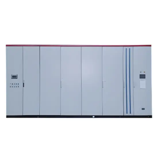
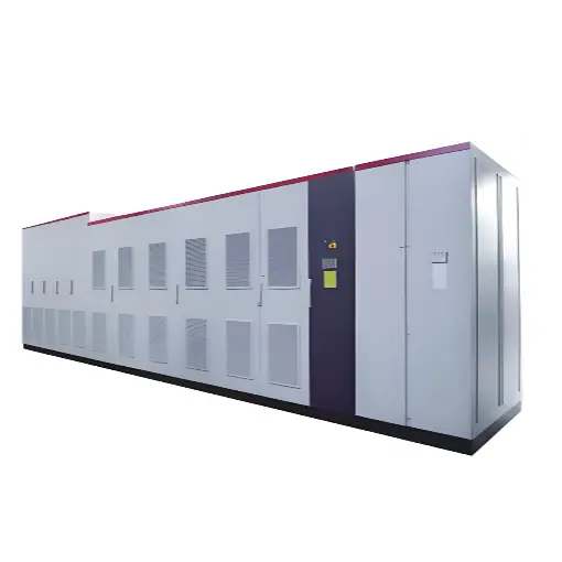
High-Voltage Motor Soft Starter & Variable Frequency Drive System 6kV 10kV
Rated voltage
6kV
Rated power
300W
Series
RW
Product descriptions from the supplier
Description
Product Overview
High-voltage motor starting and variable frequency drive systems are widely used in large-scale industrial applications, providing smooth motor startup, speed regulation, energy-saving control and operational protection.They are ideal for driving major mechanical equipment such as:
Fans & blowers
Water pumps
Air compressors
Steel rolling mills
Centrifuges and crushers
Industrial process machinery
These systems are extensively deployed in industries including:
Mining and mineral processing
Petrochemical plants
Municipal water supply and infrastructure
Metallurgy and steelworks
Power generation and energy systems
By enabling soft starting and adjustable speed operation, they effectively reduce starting current impact, improve process efficiency, minimize mechanical stress, extend equipment service life, and significantly lower power consumption in motor-driven applications.
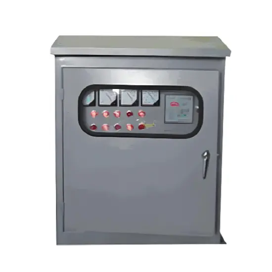
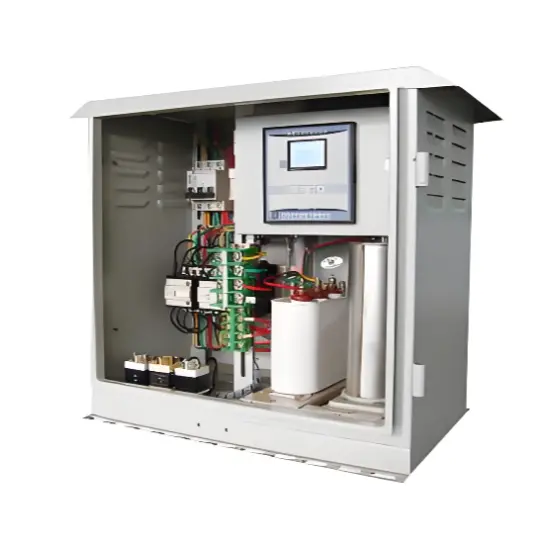
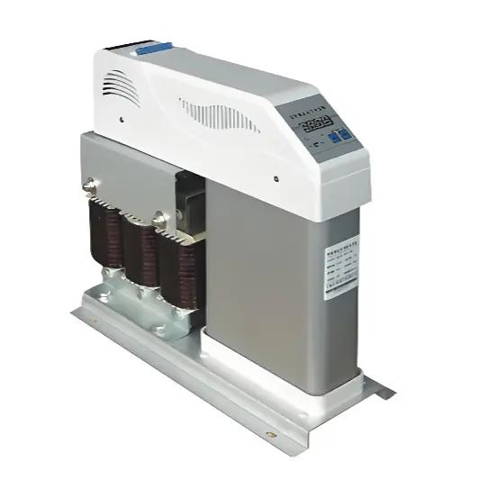
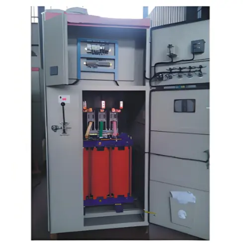
System Composition & Cabinet Structure
Section
Features
Bypass Cabinet
Enables automatic/manual switching to bypass VFD Supports system bypass operation during fault conditions Ensures production continuity
Transformer Cabinet
Includes isolation transformer, temperature sensors, current and voltage detection devices Provides stable three-phase power supply Protection functions: overload, over-current, overheat Independent cooling duct design to extend lifespan
Power Unit Cabinet
Modular power cells with standardized structure High dust & humidity resistance Optical fiber communication for high EMC immunity Scalable multi-cell parallel configuration
Control Cabinet
ARM + FPGA + DSP control cores 7-inch HMI multilingual interface Remote monitoring & expansion support Passed EMC & vibration certifications
Workplace: 30000m² Total staff: Highest Annual Export(usD): 100000000
Services
Business Type: Design/Manufacture/Sales
Main Categories: High Voltage Electrical Apparatus/Low Voltage Electrical Apparatus/Instrument meters/New energy/Tester/Robot
Whole life care manager
Whole-life care management services for equipment procurement, use, maintenance, and after-sales, ensuring safe operation of electrical equipment, continuous control, and worry-free electricity consumption.
The equipment supplier has passed platform qualification certification and technical evaluation, ensuring compliance, professionalism, and reliability from the source.
1. Accident Record (March 19, 2019)At 16:13 on March 19, 2019, the monitoring background reported a light gas action of No. 3 main transformer. In accordance with the Code for Operation of Power Transformers (DL/T572-2010), operation and maintenance (O&M) personnel inspected the on-site condition of No. 3 main transformer.On-site confirmation: The WBH non-electrical protection panel of No. 3 main transformer reported a Phase B light gas action of the transformer body, and the reset was ineff
Characteristics and Detection Devices for Single-Phase Ground Faults1. Characteristics of Single-Phase Ground FaultsCentral Alarm Signals:The warning bell rings, and the indicator lamp labeled “Ground Fault on [X] kV Bus Section [Y]” illuminates. In systems with a Petersen coil (arc suppression coil) grounding the neutral point, the “Petersen Coil Operated” indicator also lights up.Insulation Monitoring Voltmeter Indications:The voltage of the faulted phase decreases (in
The arrangement of neutral point grounding operation modes for 110kV~220kV power grid transformers shall meet the insulation withstand requirements of transformer neutral points, and shall also strive to keep the zero-sequence impedance of substations basically unchanged, while ensuring that the zero-sequence comprehensive impedance at any short-circuit point in the system does not exceed three times the positive-sequence comprehensive impedance.For 220kV and 110kV transformers in new constructi
Why Do Substations Use Stones, Gravel, Pebbles, and Crushed Rock?In substations, equipment such as power and distribution transformers, transmission lines, voltage transformers, current transformers, and disconnect switches all require grounding. Beyond grounding, we will now explore in depth why gravel and crushed stone are commonly used in substations. Though they appear ordinary, these stones play a critical safety and functional role.In substation grounding design—especially when multiple gr
Why Does the Transformer Core Need to Be Grounded?During operation, the transformer core, along with the metal structures, parts, and components that fix the core and windings, are all situated in a strong electric field. Under the influence of this electric field, they acquire a relatively high potential with respect to ground. If the core is not grounded, a potential difference will exist between the core and the grounded clamping structures and tank, which may lead to intermittent discharge.I
I. What is a Neutral Point?In transformers and generators, the neutral point is a specific point in the winding where the absolute voltage between this point and each external terminal is equal. In the diagram below, pointOrepresents the neutral point.II. Why Does the Neutral Point Need Grounding?The electrical connection method between the neutral point and earth in a three-phase AC power system is called theneutral grounding method. This grounding method directly affects:The safety, reliabilit
Haven't found the right supplier yet? Let matching verified suppliers find you.Get Quotation Now
Haven't found the right supplier yet? Let matching verified suppliers find you. Get Quotation Now
×
Send inquiry
Download
Get the IEE Business Application
Use the IEE-Business app to find equipment, obtain solutions, connect with experts, and participate in industry collaboration anytime, anywhere—fully supporting the development of your power projects and business.