| Brand | Rw Energy |
| Model NO. | Low-Voltage Dynamic Reactive Power Compensation System |
| Rated voltage | 400V |
| Rated frequency | 50/60Hz |
| Series | HYTBBDL |
Description
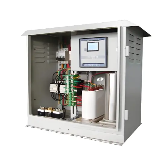
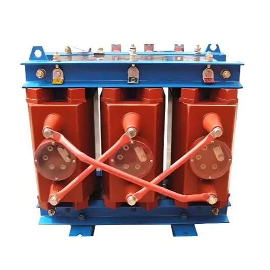
In power distribution systems where the load varies frequently, the required reactive power compensation also changes dynamically. Traditional fixed-type compensation devices are no longer able to meet the compensation demands of such applications.
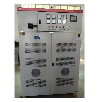
The HYTBBD Low-Voltage Dynamic Reactive Power Compensation System is specifically engineered for variable-load environments. It automatically tracks load variation in real time and provides fast-response reactive power compensation to maintain the power factor at an optimal level at all times.
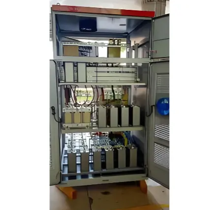
Designed with a modular architecture, the system supports flexible configuration, easy installation, convenient maintenance, and seamless future expansion. Its performance-to-cost ratio is highly competitive, making it suitable for a wide range of industrial power networks requiring dynamic compensation capability.
Model Code Description
Example: HYTBBDL-0.4-□/□W-P7
| Code | Description |
|---|---|
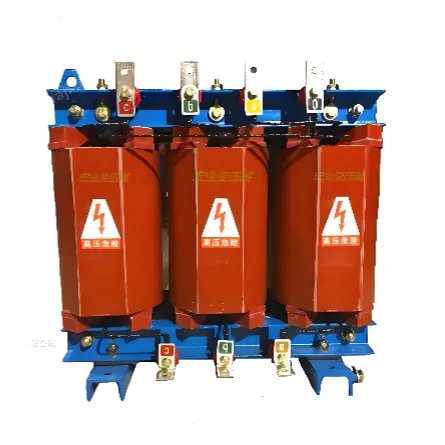
| P | Reactor |
| H | Harmonic filter branch |
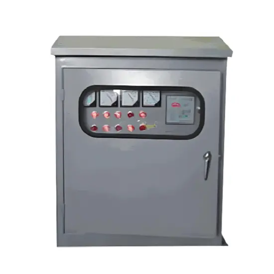
| W | Outdoor cabinet structure |
| □ | Number of capacitor groups |
| □ kvar | Rated reactive compensation capacity |
| 0.4 kV | System voltage level |
| Type 2 | L: Filter compensation / W: Line compensation |
| Type M | Standard type (M), typically omitted |
| Type 1 | J: Static / D: Dynamic |
| HYTBBD | Dynamic reactive power compensation unit |
Application Fields
The HYTBBD dynamic reactive power compensation system is suitable for industries with large variations in inductive load, such as metallurgy, machinery, mining, building materials, petrochemical, municipal facilities, and other power distribution systems with strong load fluctuation.
Main Functions
Performance Features
Working Principle
The HYTBBD system adopts advanced control algorithms with real-time sampling of reactive demand.
According to system load variation, the controller intelligently switches capacitor groups using dynamic switching devices.It suppresses inrush current and harmonic resonance, prevents over-voltage during capacitor engagement, enhances switching smoothness, and significantly reduces capacitor stress during operation.
The optimized switching extends capacitor service life while ensuring the power factor remains within the optimal range.
Technical Specifications
| Item | Specification |
|---|---|
| Rated voltage | AC380V ~ AC1140V ±15% |
| Rated frequency | 50Hz / 60Hz ±4% |
| Target power factor | ≥ 0.95 |
| Rated capacity per group | 15–60 kvar (dynamic switching) |
| Operation mode | Continuous |
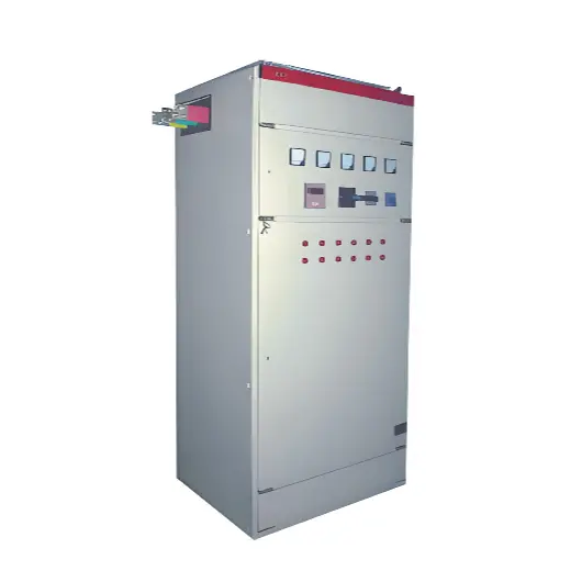
| Cabinet installation | Floor-standing |
| Environmental temp. | -10°C ~ +45°C |
| Relative humidity | ≤95%, non-condensing |
| Altitude | ≤4000m (above 2000m derating applies) |
| Protection level | IP30 |
Selection Requirements
To correctly configure the system, please provide: