• Product
  • Suppliers
  • Manufacturers
  • Solutions
  • Free tools
  • Knowledges
  • Experts
  • Communities
Search


10KW Wind&PV Hybrid Controller

  • 10KW Wind&PV Hybrid Controller
  • 10KW Wind&PV Hybrid Controller

Key attributes

Brand Wone Store
Model NO. 10KW Wind&PV Hybrid Controller
Input Voltage DC120V
Power 10KW
Series WWS-100

Product descriptions from the supplier

Description

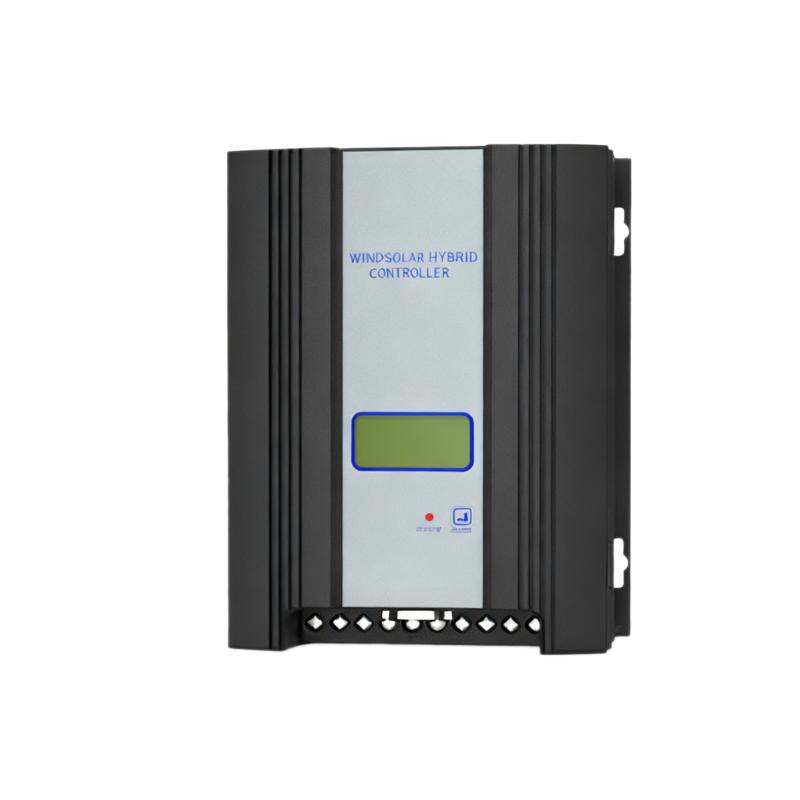
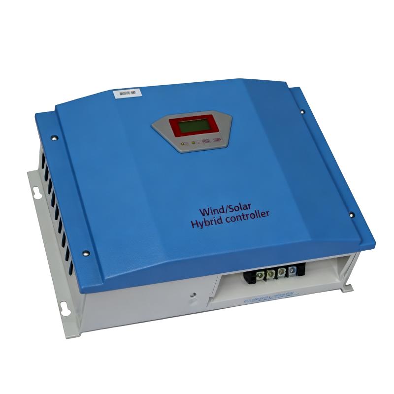
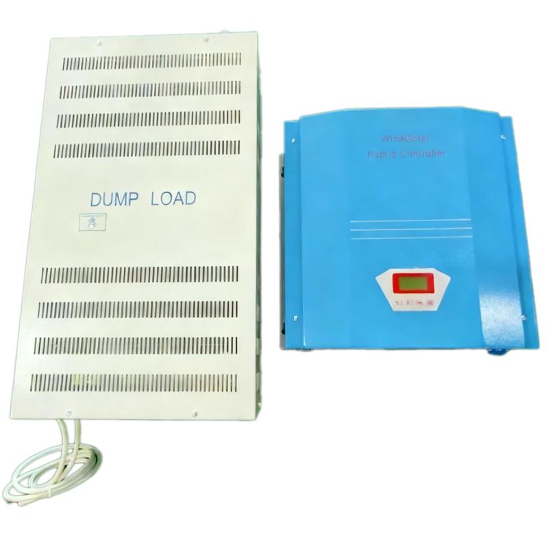
The wind/solar hybrid controller is control device which can control wind turbine and solar panel at the same time and transform wind and solar energy into electricity then store to the battery bank. Wind/solar hybrid controller is the most important part in off-grid system, whose performance has much effect on life expectancy and operation of the whole system, especially the battery expectancy. Life span of battery will be shortened by over charge or over discharge in any case.

Features

  •  Can be applied to wind&solar hybrid off-grid system

  •  Several functions are optional, such as wind speed measure function, rotational speed control function and temperature compensation function.

  •  RS232/RS485/RJ45/GPRS/Bluetooth/Zigbee optional. ( It can be monitored by app for those with GPRS/WIFI/Bluetooth connection)

Applications

  •   Independent wind power plant

  •   Independent household wind power generation system

  •   Power supply for those unmanned regions like mobile communication station, high way, the coastal islands, remote mountainous regions and border posts.

  •   Regional research projects, government demonstration projects, landscape lighting projects for those places with insufficient power or power shortages.

 Technical Parameters  

Model

WWS100-240

WWS100-120

Wind Turbine Input

Rated input power

10kW

10kW

Rated input voltage

240VDC

120VDC

Input voltage range

0~320VDC

0~160VDC

Rated input current

42A

84A

Brake by hand

Press button "Enter"    "Esc" at the same time to unload completely. Then recover by hand.

Brake by over current

42A  (factory   default, 0~42A settable) unload completely when reached the set current, and   recover automatically after working 10mins.

84A  (factory   default, 0~84A settable) unload completely when reached the set current, and  recover automatically after working 10mins.

Brake by overvoltage

Refer to "output overvoltage" control

Brake by over wind speed (optional)

14m/s  (0-30m/s   settable), unload completely when reached the set wind speed, and recover   automatically after working 10mins.

Brake by over rotational Speed (optional)

500r/min (factory default,0~1000r/min settable)Unload   completely when reached the set rotational speed, and recover automatically   after working 10mins.

PV Input  (optional)

Rated input power

3000W

3000W

Max. Open circuit voltage

480VDC

240VDC

Rated input current

13ADC

25ADC

Reversed connection protection

YES

Charge Parameters   (optional)

Rated battery voltage

240VDC

120VDC

Temperature compensation function (optional)

-3mV/℃/2V

Output Parameters

Rated output voltage

240Vdc

120VDC

Output overvoltage point

290VDC

145VDC

Output overvoltage recovery point

Less than output overvoltage

General Parameters

Rectifier mode

Uncontrolled rectifier

Display mode

LCD

Display information

DC output voltage, wind turbine   voltage/current/power/battery voltage and PV power/voltage/current

Monitoring mode (optional)

RS232/RS485/RJ45/GPRS/Bluetooth/Zigbee

Monitoring Contents

Real-time display:DC output voltage, wind turbine   voltage/current/power/battery voltage and PV power/voltage/current
Parameter setting: Output overvoltage point, wind turbine over current point,   and wind turbine brake settings.

Lightning protection

YES

Conversion efficiency

<95%

Static loss

<7W

Ambient temperature

-20℃~+40℃

Humidity

5%~95%, No condensing

Noise

≤65dB

Cooling mode

Natural cooling

Installation mode

Wall-mounted

Cover protection class

IP42

Product dimension (W*H*D)

440x305x170 mm

Product net weight

9kG

Dump load dimension(W*H*D)

520x550x430mm

Dump load weight

45kG

Note:  the listed specs are just for your   reference

Know your supplier
Online store
On-time delivery rate
Response time
100.0%
≤4h
Company overview
Workplace: 1000m² Total staff: Highest Annual Export(usD): 300000000
Workplace: 1000m²
Total staff:
Highest Annual Export(usD): 300000000
Services
Business Type: Sales
Main Categories: Wire cable/High Voltage Electrical Apparatus/Low Voltage Electrical Apparatus/Instrument meters/New energy/Tester/Integrated Electrical Equipment/Production equipment/Generator/Electrical fittings/Instrument Transformer/Equipment Parts
Whole life care manager
Whole-life care management services for equipment procurement, use, maintenance, and after-sales, ensuring safe operation of electrical equipment, continuous control, and worry-free electricity consumption.
The equipment supplier has passed platform qualification certification and technical evaluation, ensuring compliance, professionalism, and reliability from the source.

Related Products

Related Knowledges

  • HECI GCB for Generators – Fast SF6 Circuit Breaker
    1.Definition and Function1.1 Role of the Generator Circuit BreakerThe Generator Circuit Breaker (GCB) is a controllable disconnect point located between the generator and the step-up transformer, serving as an interface between the generator and the power grid. Its primary functions include isolating generator-side faults and enabling operational control during generator synchronization and grid connection. The operating principle of a GCB is not significantly different from that of a standard c
    01/06/2026
  • Distribution Equipment Transformer Testing, Inspection, and Maintenance
    1.Transformer Maintenance and Inspection Open the low-voltage (LV) circuit breaker of the transformer under maintenance, remove the control power fuse, and hang a “Do Not Close” warning sign on the switch handle. Open the high-voltage (HV) circuit breaker of the transformer under maintenance, close the grounding switch, fully discharge the transformer, lock the HV switchgear, and hang a “Do Not Close” warning sign on the switch handle. For dry-type transformer maintenance: first clean the porcel
    12/25/2025
  • How to Test Insulation Resistance of Distribution Transformers
    In practical work, insulation resistance of distribution transformers is generally measured twice: the insulation resistance between thehigh-voltage (HV) windingand thelow-voltage (LV) winding plus the transformer tank, and the insulation resistance between theLV windingand theHV winding plus the transformer tank.If both measurements yield acceptable values, it indicates that the insulation among the HV winding, LV winding, and transformer tank is qualified. If either measurement fails, pairwise
    12/25/2025
  • Design Principles for Pole-Mounted Distribution Transformers
    Design Principles for Pole-Mounted Distribution Transformers(1) Location and Layout PrinciplesPole-mounted transformer platforms should be located near the load center or close to critical loads, following the principle of “small capacity, multiple locations” to facilitate equipment replacement and maintenance. For residential power supply, three-phase transformers may be installed nearby based on current demand and future growth projections.(2) Capacity Selection for Three-Phase Pole-Mounted Tr
    12/25/2025
  • Transformer Noise Control Solutions for Different Installations
    1.Noise Mitigation for Ground-Level Independent Transformer RoomsMitigation Strategy:First, conduct a power-off inspection and maintenance of the transformer, including replacing aged insulating oil, checking and tightening all fasteners, and cleaning dust from the unit.Second, reinforce the transformer foundation or install vibration isolation devices—such as rubber pads or spring isolators—selected based on the severity of vibration.Finally, strengthen sound insulation at weak points of the ro
    12/25/2025
  • Risk Identification and Control Measures for Distribution Transformer Replacement Work
    1.Electric Shock Risk Prevention and ControlAccording to typical design standards for distribution network upgrades, the distance between the transformer’s drop-out fuse and the high-voltage terminal is 1.5 meters. If a crane is used for replacement, it is often impossible to maintain the required minimum safety clearance of 2 meters between the crane boom, lifting gear, slings, wire ropes, and the 10 kV live parts, posing a severe risk of electric shock.Control Measures:Measure 1:De-energize th
    12/25/2025

Related Solutions

  • Dedicated Vacuum Contactor Solution for Port Shore Power Systems
    I. Background and Challenges​Shore power systems have become core technical equipment for ports to reduce carbon emissions and noise pollution. However, these systems face two major challenges in the harsh operational environment of ports:​Severe Environmental Corrosion: High humidity and salt spray in port areas cause serious corrosion to metal components and enclosures of electrical equipment, significantly impacting electrical lifespan and operational reliability.​High Switching Requirements:
    09/13/2025
  • ABB Vacuum Contactor KC2 Power Supply System Technical Transformation Plan
    Issue Overview​The 10kV air compressor starting system of a company utilizes the ABB vacuum contactor KC2 as the control component for the operating circuit. The dedicated wide-voltage power supply module paired with this contactor presents the following issues:​Frequent failures: The power supply module fails to properly transition the voltage from 300V to 12V, resulting in fuse blowouts.​Poor heat dissipation: Enclosed installation of the module leads to insufficient heat dissipation, acceler
    09/13/2025
  • Solution for Medium-Voltage Motor Control and Protection Using Vacuum Contactor-Fuse (VCF) in a Coal Conveying System
    1.Project BackgroundA coal conveying system comprises 15 belt conveyors driven by medium-voltage motors. The system operates under complex conditions, with motors often subjected to heavy loads and frequent starts. To address these challenges and achieve effective control and reliable protection during motor startup, the project comprehensively adopts Vacuum Contactor-Fuse (VCF) combination devices for the 6kV medium-voltage motor power distribution. This solution details the technical features,
    09/13/2025
Haven't found the right supplier yet? Let matching verified suppliers find you. Get Quotation Now
Haven't found the right supplier yet? Let matching verified suppliers find you.
Get Quotation Now
Send inquiry
Download
Get the IEE Business Application
Use the IEE-Business app to find equipment, obtain solutions, connect with experts, and participate in industry collaboration anytime, anywhere—fully supporting the development of your power projects and business.