• 1000-1600A DNH40 Series Disconnector Switch
1000-1600A DNH40 Series Disconnector Switch
discuss personally
Model
DNH40-AC1000V/1600A
DNH40-AC1000V/1250A
DNH40-AC1000V/1000A
Basic info
Brand Switchgear parts
Model NO. 1000-1600A DNH40 Series Disconnector Switch
Rated voltage AC 1000V
Rated normal current 1600A
Rated frequency 50Hz
Series DNH40
Product Detail

The DNH40 series disconnector switch (hereinafter referred to as "the switch") is suitable for industrial power distribution systems with AC 50Hz/60Hz and rated insulation voltage up to 1000V. It is designed for infrequent circuit connection/disconnection and electrical isolation, widely used in construction, power, petroleum, chemical, and automation systems.

Isolator Switches Feature

1、Modular Design

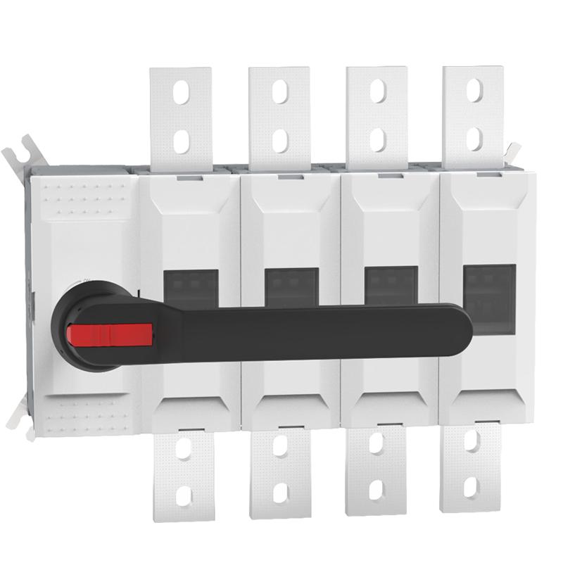
The DNH40 series features a modular structure that can be assembled according to customer requirements.

2、Durable Construction

The switch housing is made of glass fiber-reinforced unsaturated polyester resin, offering excellent flame-retardant properties, dielectric performance, anti-carbonization, and impact resistance.

3、Efficient Operating Mechanism

Equipped with a double spring energy storage mechanism, the switch allows instantaneous release of th spring during operation, ensuring quick connection and disconnection. This mechanism is independent of the operating handle speed, significantly enhancing the switching capabilities.

4、Rotary Contact Structure

The rotary multi-breakpoint contact structure ensures a safe isolation distance, meeting the reliable isolation requirements.

5、Visual Indicator

The position of the moving contact is visible through a window, providing a higher level of safety.

6、Clear Status Indication

The switch features a clear ON/OFF indicator. When in the “O” position, the handle can be locked to prevent accidental operation.

Isolator Switches Application

1、Machinery and Equipment

Suitable for machinery that requires infrequent connection and disconnection of circuits. The reliable isolation ensures safety during maintenance and operation.

2、Distribution Systems

Used in electrical distribution systems to isolate different sections for maintenance or in case of a fault. Ensures the safety of personnel and equipment.

3、Switchgear and Control Panels

Integral to switchgear and control panels for safe isolation of circuits. Ensures that operators can safely work on electrical panels without the risk of electric shock.

4、Motor Control Centers

Provides isolation for motor control circuits, allowing safe maintenance and operation. Essential in industrial environments where motor control is critical.

5、Photovoltaic Systems

Used in photovoltaic systems to isolate parts of the system for maintenance, ensuring safety and reliability in renewable energy setups.

Key Technical Parameters

Model   DNH40 - 1000 DNH40 - 1250 DNH40 - 1600
Conventional thermal current and rated operational current A 1000 1250 1600
Rated operational voltage (AC - 20/DC - 20) V 1000 1000 1000
Rated insulation voltage (Installation category Ⅳ) Ui V 1000 1000 1000
Dielectric strength 50Hz 1min kV 10 10 10
Rated impulse withstand voltage Uimp kV 12 12 12
Rated operational current (AC - 21A) 690V A 1000 1250 1600
Rated operational current (AC - 22A) 690V A 1000 1250 1600
Rated operational current (AC - 23A) 690V A 1000 1250 1250
Power loss per pole (at rated operational current) W 19 29 48
Rated short - time withstand current ≤690V1s kA 50 50 48

Normal Operating Conditions

Ambient Temperature Range: -5°C to +40°C, with a 24-hour average temperature not exceeding +35°C
Humidity At maximum temperature (+40°C), relative humidity ≤ 50%. At lower temperatures (e.g., +20°C), higher humidity (up to 90%) is permissible. Special measures must be taken to address occasional condensation caused by temperature fluctuations.
Altitude ≤2000m
Pollution Degree III
Installation Category IV
Installation Requirements The switch must be installed in a location free from significant vibration, mechanical shock, or exposure to rain/snow. The installation site must be free of explosive hazardous substances and corrosive gases/dust that could damage metal or insulation.
Note If the switch is intended for use in ambient temperatures exceeding +40°C or below -5°C, the user must consult the manufacturer.

Know your supplier
Switchgear parts
VoltEdge Solutions​​ specializes in manufacturing premium ​​MV switchgear accessories​​ for global power distribution systems. Our product range includes circuit breaker modules, disconnector spares, and surge arrestors, engineered for ​​24kV+ substations​​ and renewable energy plants. With ISO-certified production and 24/7 technical support, we ensure ​​reliability, compliance​​ with IEC standards, and rapid global supply.
Main Categories
Electrical fittings/Equipment Parts/Low Voltage Electrical Apparatus
Business Type
Sales
Highest Annual Export (USD)
$300000000
Professional Experience
1 years
Workplace
1000m²
占位
占位
Related Products
Related Knowledges
Ensuring Reliability: A Deep Dive into Transformer Maintenance
IntroductionElectric transformers are the backbone of modern power distribution systems, silently enabling the reliable delivery of electricity to homes, businesses, and industries. As these critical assets age and the demand for uninterrupted power grows, the importance of diligent transformer maintenance has never been greater. This essay explores the essential role of transformer maintenance, highlighting the value of proactive care, the impact of advanced diagnostic technologies, and the tra
Vziman
09/03/2025
How does a transformer work?
Transformer Operation PrincipleA transformer is an electrical device that operates on the principle of electromagnetic induction to transfer electrical energy from one circuit to another. It enables the adjustment of voltage levels within an alternating current (AC) system, either stepping up (increasing) or stepping down (decreasing) voltage while maintaining the same frequency.Working Principle:Basic ComponentsA transformer consists of two coils, known as windings—the "primary winding" connect
Rockwell
09/03/2025
Constant testing of high-voltage cable lines
1. Definition of High-Voltage Cable Line Constant TestingHigh-voltage cable line constant testing refers to the systematic measurement, using specialized instruments, of electrical parameters such as resistance, inductance, capacitance, and conductance before a cable line is commissioned or after major maintenance. The aim is to obtain fundamental data characterizing the electromagnetic properties of the cable, serving as a critical testing phase that provides accurate parameter support for powe
Oliver Watts
09/03/2025
Technical Analysis of 220 kV High-Voltage Cable Construction in Winter
1.Work Environment Requirements and Safeguard MeasuresBased on technical requirements for cable equipment storage, laying, transportation, laying, transposition, testing, and cable terminations, the project owner and construction units have conducted extensive trials and implemented protective measures regarding ambient temperature, humidity, bending radius, traction control, and route optimization. These measures ensure high-voltage cable quality and on-site safety under harsh winter conditions
James
09/03/2025
Withstand voltage test of high-voltage cables
Withstand voltage test is an insulation test, but it is a destructive test that can reveal insulation defects difficult to detect in non-destructive testing.The test cycle for high-voltage cables is three years, and it must be conducted after non-destructive tests. In other words, the withstand voltage test is performed only after all non-destructive tests have been passed.Most high-voltage cables used today are cross-linked polyethylene (XLPE) cables, which can have large cross-sections and cov
Oliver Watts
09/03/2025
Analysis of Abnormal Causes of High-Voltage Cable Grounding Circulation and Typical Cases
I. Introduction to Cable Grounding Loop CurrentCables rated 110 kV and above use a single-core structure. The alternating magnetic field generated by the operating current induces a voltage on the metallic sheath. If the sheath forms a closed circuit through the earth, a grounding loop current will flow on the metallic sheath. Excessive grounding loop current (loop current exceeding 50 A, more than 20% of the load current, or a ratio of maximum-to-minimum phase current greater than 3) not only a
Felix Spark
09/03/2025
×
Inquiry
Download
IEE-Business is dedicated to serving the personnel in the global power industry.
Join IEE-Business, not only can you discover power equipment and power knowledge, but also canhnd like - minded friends!