Induction voltage regulators are classified into three-phase AC and single-phase types.
The structure of a three-phase induction voltage regulator is similar to that of a three-phase wound-rotor induction motor. The key differences are that the rotor’s rotation range in an induction voltage regulator is limited, and its stator and rotor windings are interconnected. The internal wiring diagram of a three-phase induction voltage regulator is shown in Figure 2-28(a), which illustrates only one phase.
When three-phase AC power is applied to the stator of the induction voltage regulator, a rotating magnetic field is generated in the air gap between the stator and rotor. This rotating magnetic field cuts both the stator winding—inducing a stator EMF—and the rotor winding—inducing a rotor EMF. The phase of the induced EMF in the rotor remains constant, while the phase of the induced EMF in the stator changes as the rotor rotates. Since the stator and rotor windings are connected together, the output voltage equals the sum of the stator and rotor induced voltages. Because the phase of the stator voltage can be varied by rotor rotation, the magnitude of the total output voltage changes accordingly, thereby achieving voltage regulation.
This principle is illustrated in Figure1, As shown in Figure 1, when the stator-induced EMF is in phase with the rotor-induced EMF, the output voltage reaches its maximum value—twice the individual induced EMF. When the phase difference between the stator and rotor EMFs is 180°, the output voltage becomes zero. This explains why the rotor of an induction voltage regulator only needs to rotate within a limited angular range—sufficient to vary the phase difference between the stator and rotor induced EMFs from 0° to 180°.

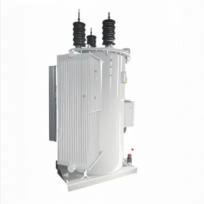
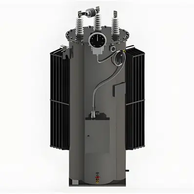
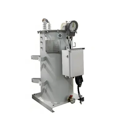
The structure of a single-phase induction voltage regulator is shown in Figure 2. The primary winding is mounted on the stator, and a short-circuited compensating winding is placed perpendicular to it. The secondary series-connected winding is located on the rotor. The magnetomotive force of the primary winding produces a single-phase pulsating magnetic field in the air gap of the stator-rotor core. As the rotor rotates within a 0° to 180° range, the induced EMF in the secondary winding varies, resulting in a smooth, stepless change in output voltage and thus achieving voltage regulation.

To prevent vibration and noise caused by overload surges or unbalanced magnetic pull, the gear mechanism is equipped with safety shear pins and elastic vibration-damping pads.
The short-circuit impedance voltage variation ratio of an induction voltage regulator is very large. Consequently, the output voltage may rise abruptly if the load current suddenly decreases—this requires special attention. The output power of an induction voltage regulator decreases as the output voltage is reduced. Therefore, overloading must be avoided during operation, and the secondary output current must not exceed its rated value. If the input terminals of an induction voltage regulator are left open-circuited while the output terminals are connected to a circuit, it functions as a variable inductor.
In a three-phase induction voltage regulator, both the magnitude and phase of the output voltage change simultaneously. Therefore, three-phase induction voltage regulators must never be operated in parallel.