| Brand | ROCKWILL |
| Model NO. | Continuous / Step voltage regulation step voltage regulator 6kV 6.35kV 11kV 15kV 22kV 33kV – IEEE |
| Rated voltage | 11kV |
| Rated frequency | 50/60Hz |
| Phases | Single-phase |
| Series | RVR |
Product Overview
As a pioneer and the first source factory in China's voltage regulator industry, we have been deeply rooted in the sector for decades, accumulating profound technical expertise. Leveraging top-tier R&D capabilities and a mature manufacturing system, our products have gained widespread market trust with reliability and performance that far exceed industry standards.
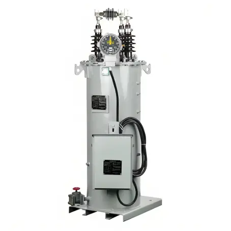
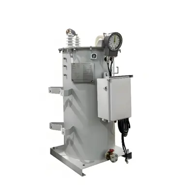
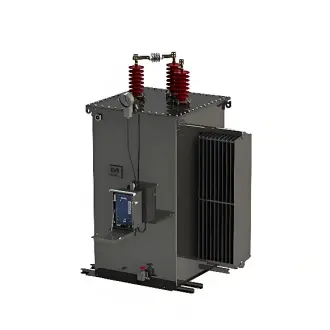
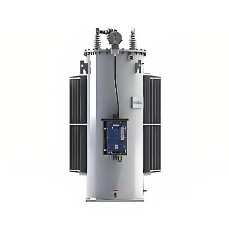
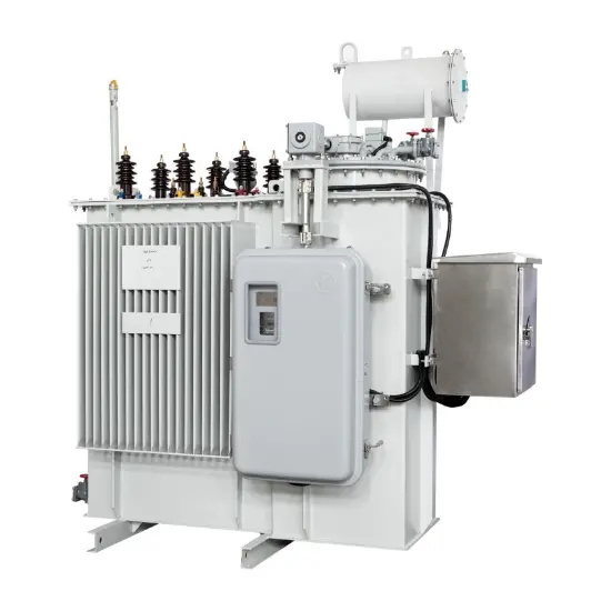
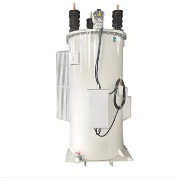
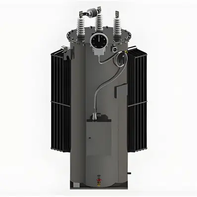
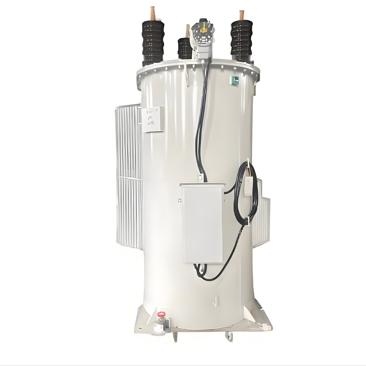
The RVR-1 single-phase step voltage regulator is an oil-immersed autotransformer with an integrated on-load tap changer, designed to automatically stabilize distribution line voltage. It offers ±10% regulation in 32 fine steps (approximately 0.625% each), ensuring consistent voltage across varying load conditions.
Voltage ratings range from 2,500V (60 kV BIL) to 19,920V (150 kV BIL), with current capacities from 50A to 1665A and kVA ratings from 38.1 to 1000. The unit is compatible with both 50Hz and 60Hz systems and can be pole-mounted, pad-mounted, or installed in substations.
Product Features
Precise Step Voltage RegulationOffers a ±10% wide voltage adjustment range, achieved through 32 automatic and precise tap positions—each calibrated to approximately 0.625%. This fine-step design enables real-time response to grid voltage fluctuations, ensuring the output voltage is stabilized within a high-precision range, effectively compensating for line voltage drops and meeting the strict voltage quality requirements of industrial and commercial loads.
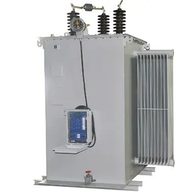
Intelligent Digital ControllerFeatures a high-performance programmable digital controller with user-friendly configuration options. Supports optional GPRS/GSM/Bluetooth communication protocols for seamless remote monitoring, parameter adjustment, and fault diagnosis. Built-in data logging functionality automatically records key operating parameters (e.g., voltage, current, tap position, fault codes) with timestamped records, facilitating maintenance analysis and system optimization for enhanced operational efficiency.
Flexible Installation ConfigurationsDesigned for versatile deployment across power system scenarios:
Pole mounting: Compatible with standard utility poles via dedicated mounting brackets, ideal for overhead distribution lines (e.g., rural power grids, industrial park feeders);
Pad-mount installation: Equipped with a robust ground-mounted base for stable placement in outdoor open areas or near load centers;
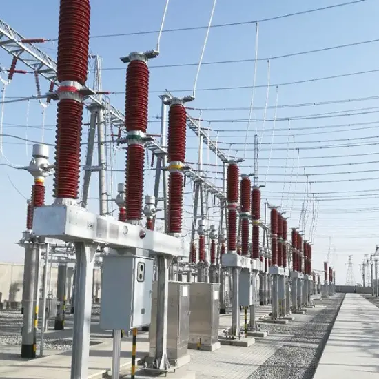
Substation mounting: Optional elevating platforms available for integration into substation equipment layouts, adapting to indoor or outdoor substation environments.
All installation options comply with power industry safety standards, ensuring easy assembly and reliable operation in diverse conditions.
Technical Specifications
Available voltage ratings include 50Hz (6kV, 6.35kV, 11kV, 15kV, 22kV, 33kV) and 60Hz (7.62kV, 13.8kV, 14.4kV, 19.92kV, 34.5kV). Custom voltage ratings are available upon request.
Parameter |
Specification |
Model No. |
RVR-1 |
Rated Voltage |
7.62 kV |
Voltage Regulation Range |
±10% (Boost/Buck) |
Tap Steps |
32 steps (approx. 0.625% per step) |
Phase |
Single-phase |
Rated Frequency |
50 Hz / 60 Hz |
Rated Current |
50 A - 1665 A |
Rated Capacity (kVA) |
38.1 - 1000 kVA |
BIL (Basic Impulse Level) |
60 - 150 kV |
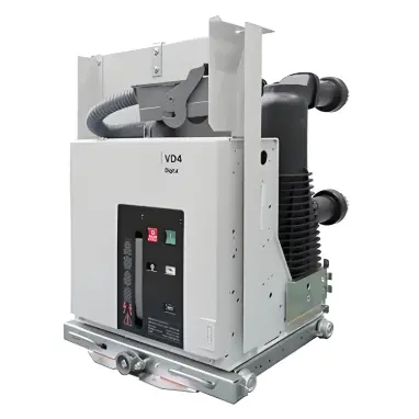
Transformer Type |
Oil-immersed autotransformer with on-load tap changer |
Cooling Method |
ONAN (Oil Natural Air Natural) |
Winding Type |
Two-winding Transformer |
Core Shape |
Ring type |
50Hz
Voltage (kV) |
Current (A) |
Capacity (kVA) |
BIL (kV) |
Power Frequency Withstand Voltage (kV) |
Insulation Class |
6/6.35 |
50 |
30/32 |
75/95 |
28 |
A |
100 |
60/64 |
||||
150 |
90/95 |
||||
200 |
120/127 |
||||
300 |
180/191 |
||||
400 |
240/254 |
||||
500 |
300/318 |
||||
600 |
360/381 |
||||
11 |
50 |
55 |
|||
100 |
110 |
||||
150 |
165 |
||||
200 |
220 |
||||
300 |
330 |
||||
400 |
440 |
||||
500 |
550 |
||||
600 |
660 |
||||
15 |
50 |
75 |
125/150 |
50 |
|
100 |
150 |
||||
150 |
225 |
||||
200 |
300 |
||||
300 |
450 |
||||
400 |
600 |
||||
500 |
750 |
||||
22 |
50 |
110 |
|||
100 |
220 |
||||
150 |
330 |
||||
200 |
440 |
||||
300 |
660 |
||||
33 |
50 |
165 |
170/200 |
70 |
|
100 |
330 |
||||
150 |
495 |
||||
200 |
660 |
||||
250 |
825 |
||||
300 |
990 |
Key Advantages
Certified Quality
ISO9001 & ISO14001 certified; each unit is fully type-tested before delivery
Robust & Reliable
Built for harsh environments with minimal maintenance requirements
Flexible Packaging Options
Export-grade seaworthy wooden boxes available in single or double-unit formats to reduce shipping cost
Professional Support
Fast pre-sales response, real-time production updates, and long-term after-sales service
Application Scenarios
Rural & Urban Distribution Networks
Compensates for voltage drops along long feeder lines
Industrial Zones
Ensures voltage stability for large machinery and sensitive equipment
Renewable Energy Integration
Maintains voltage stability in grids with wind or solar input
Substation Use
Enhances voltage control across secondary distribution systems
IEEE C57.15/C57.116 standards define critical requirements for 33kV regulators:
Testing Rigor: Mandates lightning impulse withstand (110kV) and temperature rise tests (55°C max)
Safety Protocols: Requires pressure relief devices and fault current withstand (25kA/2s)
Performance Metrics: Specifies ±0.5% voltage accuracy and 96% minimum efficiency at 50-100% load
Compliance Value: IEEE-certified models ensure grid compatibility and simplify utility approval processes
These standards directly correlate to 20% longer service life and 35% reduced maintenance costs in field deployments.
Step voltage regulators offer two distinct voltage correction methods:
Step Regulation: Adjusts voltage in fixed increments (typically ±10% range in 0.625-1.25% steps) using tap changers. Ideal for stable grids where precision adjustments are sufficient.
Continuous Regulation: Provides smooth, stepless correction through electronic power conversion. Perfect for volatile grids with frequent fluctuations (e.g., renewable integration zones).
All models (6kV-33kV) comply with IEEE C57.15 standards, with step versions featuring 32-position tap changers and continuous versions maintaining ±1% output accuracy under all load conditions.