
Isipan sa industriya ang sistema sa automatikong elektroliko nagdumala sa kabuok nga gasto sa produksyon ug impakto sa kalibutan. Ang tradisyonal nga pag-operasyon sa konstante nga bilis kasagaran mobati sa pagbati sa mga iba't ibang kahimtang sa load ug nagpadali sa maayong kontrol sa proseso. Ang teknolohiya sa pag-regulate sa bilis sa variable frequency, isip usa ka advanced nga paraan sa kontrol sa motor, naghatag og maayo nga solusyon sa mga problema niini. Kini nga pag-aaral gitukod ang sistema sa automatikong elektroliko sa usa ka planta sa kuryente isip ehempiyo aron mihatagan og pagsusi ang iskema sa pag-renovate batasan sa inverter speed control technology ug ang iyang epekto sa pag-save sa energy, ngadto sa paghatag og reference alang sa pag-improve sa energy efficiency sa parehas nga industriyal nga scenario.
1 Kasamtangan nga Kahimtang ug Mga Pangangailihan sa Pag-renovate sa Inverter Applications sa Elektrolikong Automatiko
1.1 Nag-unang Equipment
Ang sistema sa automatikong elektroliko sa planta sa kuryente pangunahan gisulay sa tulo ka bahin: ang sistema sa distribusyon sa kuryente, ang mga unit sa motor drive, ug ang sistema sa kontrol. Ang sistema sa distribusyon sa kuryente nagsama sa 10 kV high-voltage switchgear, transformers, ug 400 V low-voltage switchgear, na arrange sa tree structure alang sa distribusyon sa kuryente. Ang mga motor drives pangunahan asynchronous motors nga gi-control pinaagi sa direct-on-line o star-delta reduced-voltage starting methods. Ang pump loads adunay pinaka dako nga bahin sa on-site equipment, kasagaran circulating water pumps, cooling water pumps, ug feedwater pumps. Kini nga mga device nag-operate sa konstante nga bilis, uban sa flow regulate pinaagi sa valves, resulta sa mataas nga gasto sa energy. Ang existing system architecture mas dako ang pag-disperse, ngadto sa partial centralized management. Ang upper-level monitoring system nag-communicate sa field control systems pinaagi sa industrial Ethernet aron mahimo ang centralized data display ug remote operation. Apan, ang kasamtangan nga sistema sa kontrol wala adunay advanced nga kontrol algorithms para sa variable frequency speed regulation, nagresulta sa kawahanan sa energy management ug process optimization.
1.2 Mga Pangangailihan sa Pag-renovate
Batasan sa kasamtangan nga status sa equipment, ang mga pangangailihan sa pag-renovate sa sistema sa automatikong elektroliko pangunahan focus sa pag-improve sa energy efficiency ug pag-optimize sa kontrol. Kinahanglan i-introduce ang inverter-based speed control technology aron mahimo ang efficient nga operasyon sa pumps ug fans pinaagi sa pag-adjust sa bilis sa motor para matugotan ang load demands.
Sa parehas, gamiton ang existing pump stations ug production facilities, urgent ang kinahanglan sa pag-build og intelligent monitoring platform compliant sa Level 2 cybersecurity protection requirements. Centered sa cloud computing ug integrated sa IoT technology, kini nga platform mahimo ang seamless integration tali sa enterprise management ug field control. Ang sistema sa architecture adopt ang three-tier structure sa "central platform + distributed subsystems + mobile terminals," sigurado nga real-time data acquisition, efficient processing, ug secure storage.
Ang central platform, gitukod sa high-performance server cluster, deploy advanced nga data analysis algorithms aron hatagan og accurate decision support. Ang distributed subsystems nagsama sa modules para sa equipment condition monitoring, video surveillance, ug environmental parameter collection, comprehensively covering tanang aspeto sa production operations. Ang mobile terminals, pinaagi sa customized applications, enable remote monitoring ug instant notifications.
2 Teoretikal nga Basehan sa Epekto sa Pag-save sa Energy
Ang analisis sa epekto sa pag-save sa energy sa inverter speed control technology niining pag-aaral pangunahan basehan sa affinity laws para sa fans ug pumps ug ang energy conversion principles sa variable frequency speed regulation. Batasan sa operational status sa plant's equipment, dako ang numero sa pumps ug fans nag-operate sa konstante nga bilis uban sa flow regulate pinaagi sa valves, resulta sa significant nga energy losses. Sa katuyuan, ang variable frequency speed control adjust ang bilis sa motor para matugotan ang load requirements, resulta sa pag-save sa energy. Ang affinity laws para sa fans ug pumps gitukod batasan sa relationships tali sa flow rate, head, ug power, ang relevant nga calculation formulas as follows:

kung diin Q ang flow rate (m³/h); n ang rotational speed (r/min); H ang head (m); P ang power (kW), kung diin P1 ang rated power ug P2 ang power sa reduced speed. Ang energy conversion formula sa variable frequency speed regulation:

Batasan sa uban pa nga teoretikal nga relationships, kung ang system flow demand mobati, ang motor automatic gibabati ang bilis pinaagi sa frequency control, significantly lowering power consumption ug achieving energy savings. Kini naghatag og teoretikal nga foundation sa subsequent retrofit design ug energy-saving evaluation.
3 Retrofit Scheme sa Inverter Speed Control Technology
3.1 Power Distribution System Upgrade
Arong makaepektibo implementar ang inverter speed control technology, niining pag-aaral upgrade ang existing power distribution system. Para sa high-voltage system, ang 10 kV switchgear gi-enhance pinaagi sa pag-install sa intelligent vacuum circuit breakers nga adunay rated current nga dili babaw sa 1,250 A ug rated short-circuit breaking capacity nga 31.5 kA. Gi-integrate ang microprocessor-based protection relays, providing multi-function protection including overcurrent, short-circuit, ug ground fault, ug response time under 20 ms. Gitukod usab ang electric power quality monitoring system, using Class A-grade high-precision sensors aron monitor parameters such as harmonic content, voltage fluctuations, ug three-phase unbalance sa real time, ensuring system stability.
Para sa low-voltage system, ang 400 V system ang focus sa upgrade. Giatiman ang dedicated inverter feeder circuits sa existing system pinaagi sa independent feeder cabinets equipped sa intelligent molded-case circuit breakers. Ang rated current gi-select batasan sa 400 A hangtod 630 A batasan sa load requirements, featuring electronic trip units for precise overload ug short-circuit protection. Each inverter circuit equipped sa isolating switch matching the circuit breaker's rated current ug includes a visible break feature to facilitate equipment maintenance.
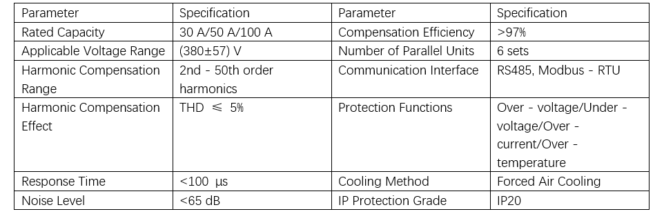
Para sa harmonic mitigation, installed ang active power filters (APF) sa inverter input side, with specific specifications as listed in Table 1.
Para sa optimization sa grounding systems, niining pag-aaral adopted ang TN-S wiring method, separating the neutral line (N) from the protective earth line (PE) starting from the distribution cabinet. The main PE line uses copper conductors with a cross-sectional area of no less than 95 mm² to ensure a ground resistance of less than 1 Ω. Equal potential bonding bars added at critical equipment locations such as inverters and motors, using copper conductors with a cross-sectional area greater than 16 mm². This effectively suppresses common-mode interference and enhances the system's EMC performance [21].
3.2 Selection and Parameter Optimization of Inverter Equipment
The selection of inverters is based on precise matching of load characteristics and process requirements. For pump loads, vector control inverters are chosen, with their rated power strictly corresponding to the motor's, and an overload capacity of 150%/1 min. This study selected the ABB ACS880 series inverter, which features DTC (Direct Torque Control) technology, with a torque response time of less than 5 ms and speed control accuracy of ±0.01%. Considering the on-site environment, a sealed inverter with an IP54 protection rating was used, equipped with a forced air cooling system, ensuring a cooling airflow of no less than 1 m³/(min·kW).
For parameter optimization, the focus is on adjusting the PID control parameters and utilizing the self-tuning algorithm built into the inverter. Through step response testing, the optimal proportional gain Kp, integral gain Ki, and derivative gain Kd are automatically calculated. The calculation formula for the PID controller output u(t) is:

The built-in auto-tuning algorithm of the inverter is used to automatically calculate the optimal proportional gain Kp (range: 0.1–100), integral time Ti (range: 0.1–3600 s), and derivative time Td (range: 0–10 s) through a step response test. Acceleration time is set to 10–30 s and deceleration time to 15–45 s to effectively prevent water hammer effects. Torque limiting is enabled with a setting of 120% of the motor's rated torque to prevent overload. For fan loads, the inverter's energy-saving mode is activated: under light-load conditions (load rate < 50%), the output voltage is automatically reduced, with a maximum reduction of up to 20%. Meanwhile, the V/F curve is optimized by increasing the voltage output in the low-speed range (0–10 Hz) to ensure sufficient starting torque.
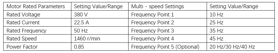
A sleep-wake function is configured: when the operating frequency remains below 10 Hz for 60 s, the inverter enters sleep mode; it automatically wakes up when the system pressure drops by 5%, further improving system efficiency. In the basic inverter settings, the carrier frequency is set to 4 kHz. Based on the actual requirements of the power plant, the overvoltage and undervoltage protection thresholds are set to 418 V and 304 V, respectively. Additionally, the motor's rated parameters and multi-speed operation settings are configured as detailed in Table 2.
The calculation formulas for current limitation and minimum current optimization are respectively as follows:

where Ilim is the maximum current limit; In is the motor rated current; Ismin is the minimum stator current; Idopt is the optimal excitation current; and Iq is the torque current component. By incorporating current limiting and minimum current optimization strategies, fine-grained control of motor operation is achieved. Overvoltage and undervoltage protection settings ensure the motor operates within a safe range. Stall protection and current limiting measures effectively prevent overload. Additionally, this control method supports communication via the Modbus-RTU protocol, enabling remote monitoring and parameter adjustment, thereby significantly enhancing the system's intelligence level.
3.3 Control System Upgrade and Integration
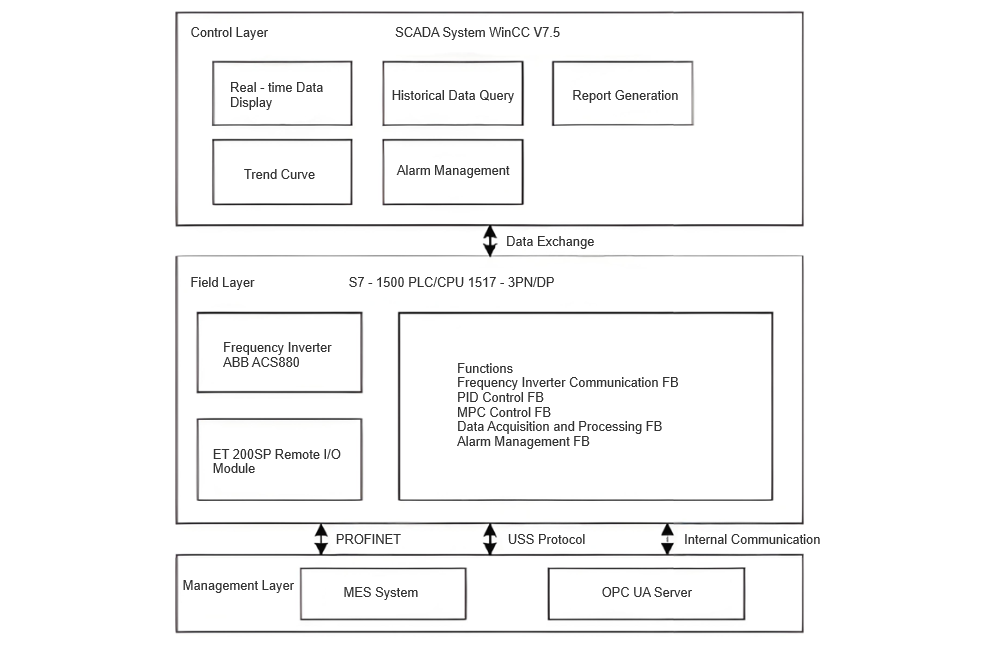
The control system upgrade employs the Siemens S7-1500 series PLC, specifically the CPU 1517-3 PN/DP model, which features a 2 ns bit operation speed and a 40 ns word operation speed. The PLC is equipped with 1.6 GB of working memory and 32 MB of load memory, supporting communication protocols including PROFINET, PROFIBUS, and OPC UA. The system adopts a distributed architecture with ET 200SP series remote I/O modules, achieving a 250 μs communication cycle via PROFINET.
The software architecture is based on the TIA Portal V16 integrated development environment. The PLC program includes function blocks (FBs) for inverter communication, PID control, Model Predictive Control (MPC), data acquisition preprocessing, and alarm management. The detailed system framework is illustrated in Figure 1.
4 Energy-Saving Effect Analysis
The energy-saving benefits of inverter speed control technology are primarily reflected in reduced power consumption and improved system efficiency. By comparing energy consumption data before and after the retrofit, the energy-saving performance can be quantitatively evaluated. The post-retrofit system data in this study were collected using the following methods:
Energy Metering System: Smart meters were installed on the power supply lines of major electrical equipment to collect electricity consumption data before and after the retrofit. The meter model is Schneider PM5560, with an accuracy class of 0.2S and a sampling interval of 15 minutes.
Inverter Built-in Functions: The built-in energy monitoring function of the ABB ACS880 inverter was used to record operating time, output power, and energy consumption. Data were transmitted to the central control room via the Modbus-RTU protocol.
SCADA System: A real-time data acquisition and storage system was built using the Siemens WinCC V7.5 platform. Key parameters such as motor speed, load rate, output voltage/current, and power factor were monitored with a 1-second sampling cycle.
On-site Testing: The Fluke 435 II power quality analyzer was used to conduct spot measurements under various load conditions, capturing instantaneous power, harmonics, and power factor data.
Based on the measured data, the annual average load rate was calculated. By comparing energy consumption before and after the retrofit, the power-saving rates under different load conditions were determined, as shown in Table 3.
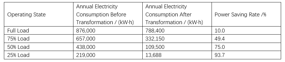
The results show that the energy-saving effect gradually increases as the load rate decreases, which aligns with the cubic law principle of energy saving in variable frequency speed control. Under full-load operation, the power-saving rate is 10%, primarily attributed to the high efficiency and precise control capability of the inverter, indicating that even under high-load conditions, frequency control technology still offers significant energy-saving potential.
At a 75% load rate, the power-saving rate increases to 49.4%, highlighting the advantages of variable speed control under partial load. When operating at 50% load, the power-saving rate reaches 75%, demonstrating its excellent performance under medium load. At 25% load, the power-saving rate reaches as high as 93.7%, fully showcasing the substantial energy-saving potential of variable speed control under low-load conditions.
Overall, the annual average power-saving rate is 56.8%, indicating that the optimized system achieves good comprehensive energy-saving performance during actual operation cycles. Considering the time distribution across different load states, these results provide valuable guidance for energy efficiency optimization in industrial electrical automation systems.
For fan loads, the inverter's built-in energy optimization function automatically adjusts the V/F curve under light-load conditions. Measurements using the Fluke 435 II power quality analyzer at various load rates reveal the relationship between voltage reduction and power consumption reduction.
Results show that in the load rate ranges of 20%–30%, 30%–40%, and 40%–50%, power consumption reductions are 36.7%, 25.3%, and 15.8%, respectively. This indicates that the lower the load rate, the greater the proportional reduction in power consumption achieved by the same degree of voltage adjustment. For ultra-light-load conditions below 20%, more aggressive control strategies or equipment shutdown should be considered to further improve overall system efficiency.
5 Conclusion
This study, through the retrofitting practice of an electrical automation system in a power plant, verifies the significant energy-saving effectiveness of variable frequency speed control technology. By optimizing control strategies and system integration, substantial reductions in power consumption and improvements in operational efficiency are achieved. The findings provide a technical reference for energy-saving retrofits in similar industrial scenarios. Future work will further consider the uncertainties in operation and travel times by developing a probabilistic operation resource scheduling model to better address various uncertainties in real-world operations.


