The operational status and reliability of equipment within substations directly affect the safety and stability of the power grid. Most substation equipment consists of metal components made from various materials such as pure copper, carbon steel, and stainless steel. During long-term operation, performance degradation of these metallic materials often leads to equipment failures, posing significant risks to the safe and stable operation of substations.
Outdoor high-voltage disconnectors are a prime example. Their proper functioning is critical—not only for the reliability, safety, and stability of substation power supply, but also because their failure can potentially trigger a collapse of the entire power grid. Therefore, it is of great significance to actively analyze the root causes of common equipment failures in substations and propose targeted protective measures.
1. Introduction to Outdoor High-Voltage Disconnectors
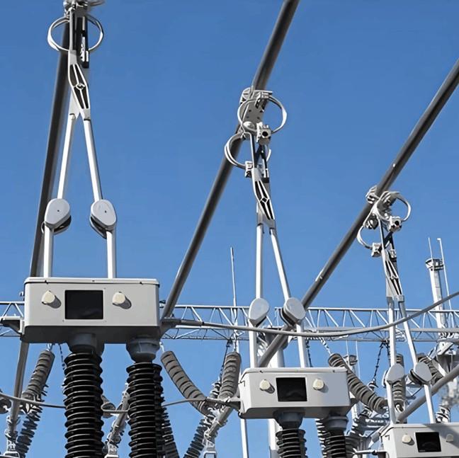
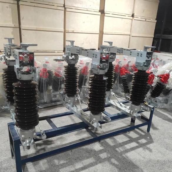
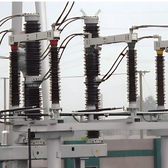
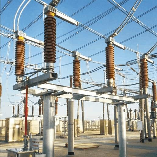
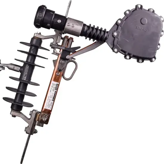
The outdoor high-voltage disconnectors at a certain 330 kV substation are early-model GW4-series products manufactured by a former high-voltage switchgear plant. They feature a double-column horizontal structure with left-right symmetry and consist of a base, support brackets, insulators, and a main conductive assembly. The main conductive assembly includes flexible connectors, terminal clamps, conductive rods, contacts, contact fingers, springs, and rain shields.
In September 2017, during routine maintenance, operators discovered that some of these outdoor disconnectors exhibited varying degrees of cracking in their support brackets, accompanied by severe corrosion. This posed a serious safety hazard during manual operation. Consequently, a macroscopic examination of the crack morphology was conducted. Additionally, microscopic metallographic analysis was performed on contaminants collected from both the clamp-side and terminal-side of the support brackets. Furthermore, a spectrometer was used to comprehensively analyze the chemical composition of the support brackets, conductive rods, and associated contaminants.
2. Inspection Results of Support Bracket Cracking
2.1 Macroscopic Morphology
The surface coating of the disconnector support brackets had peeled off, revealing severe corrosion. Obvious corrosion products were observed between the bracket and the conductive rod. The cracks exhibited characteristics of brittle fracture, with chevron ("herringbone") patterns visible on the fracture surfaces. The crack origin and propagation zones appeared black or dark gray.
Deflection measurements showed a deformation of 3.0 mm on the terminal-board side and 2.0 mm on the clamp side, confirming significant structural distortion of the bracket.
2.2 Microscopic Morphology
Microscopic metallographic analysis revealed contaminant layer thicknesses of 1.1–3.3 mm on the clamp side and 3.2–3.5 mm on the terminal-board side of the support bracket.
2.3 Spectral Analysis
Spectrometric analysis of the support bracket, conductive rod, and contaminants yielded the following key findings (see Table 1):
The support bracket contained 94.3% aluminum, indicating it was made of cast aluminum alloy.
The conductive rod contained 92.7% copper, along with trace elements, confirming it as a copper alloy tube.
The contaminants also contained 94.3% aluminum.
In humid atmospheric conditions, the aluminum (from the bracket) and copper (from the conductive rod) form a galvanic couple, triggering an electrochemical (galvanic) corrosion reaction. This process generates aluminum-ion-rich corrosion products—identified as the primary contaminant causing material degradation and eventual cracking.
| Sample Name | Element Content | |||||
| Al | Zn | Mn | Cu | Fe | Si | |
| Isolator Support | 94.3 | 0.33 | 0.39 | 2.64 | 0.76 | -- |
| Conductive Rod | 6.12 | 0.26 | < 0.017 | 92.66 | < 0.028 | 0.936 |
| Contaminant | 94.3 | 0.34 | 0.28 | 2.51 | 0.61 | 1.13 |
3. Cause Analysis and Protective Measures
3.1 Analysis of Support Bracket Cracking Causes
Generally, metal material failure can be attributed to two categories of factors:
Internal factors: related to material quality and manufacturing processes;
External factors: related to service conditions such as mechanical loading, time, temperature, and environmental media.
In power grid projects, metallic components typically undergo rigorous quality inspections—including material composition and expected service life—prior to deployment. Field experience shows that outdoor high-voltage disconnectors operate in harsh environments, and their reliability is predominantly governed by external service conditions rather than inherent material defects. Therefore, the cracking observed in this disconnector’s support bracket is not due to poor material quality but is primarily driven by environmental exposure.
The 330 kV substation is located in a northwestern region with a typical temperate semi-arid climate—characterized by dry air, abundant sunshine, and large diurnal and annual temperature variations. Winters are long and cold with minimal precipitation, while summers are short but hot.
The disconnector’s aluminum alloy support bracket has been continuously exposed to this severe atmospheric environment, subjected to strong winds, thermal cycling, ice accumulation, and occasional rainfall—conditions highly conducive to stress corrosion cracking (SCC).
SCC refers to the brittle fracture of a stressed metal component in a corrosive environment. Its occurrence requires two essential conditions: tensile stress and a specific corrosive medium.
In this case:
Tensile stresses exist downward on both sides of the bracket’s bottom centerline and upward at the center, resulting in uneven stress distribution.
This non-uniform loading induces plastic strain and dislocation slip in the metal, accelerating SCC initiation, propagation, and eventual fracture.
The bracket is made of cast aluminum alloy. In the presence of moisture and airborne dust particles that form soluble contaminants, galvanic and crevice corrosion readily occur—especially at the clamp-side gap, where water or ice can accumulate.
The synergistic effect of tensile stress and corrosive attack ultimately led to cracking.
Macroscopically, SCC fracture surfaces typically show black or gray-black crack origins and propagation zones due to corrosion, with sudden brittle fracture areas exhibiting radial patterns or chevron ("herringbone") markings—exactly matching the observed fracture morphology of the disconnector bracket. This strongly confirms that the failure mechanism was stress corrosion cracking.
As the most numerous equipment type in substations, outdoor disconnectors face significant risks when operating long-term in exposed environments—especially with the increasing deployment of unattended substations, which demand higher reliability. The following four protective strategies are proposed:
Since outdoor disconnectors are directly exposed to atmospheric conditions—and particularly vulnerable in extreme climates (e.g., alpine cold, high heat, coastal salinity, or icing zones)—installing isolation shields or protective enclosures can create a controlled micro-environment, significantly mitigating corrosion.
Given that uneven stress distribution combined with harsh environmental conditions triggered SCC, operators must intensify visual and mechanical inspections of critical components—especially base supports and clamping structures—to detect early signs of deformation, corrosion, or cracking and prevent secondary damage or safety incidents.
Condition monitoring of substation equipment is not only an efficient means to improve maintenance effectiveness but also a cornerstone of full lifecycle asset management. Advanced corrosion detection and real-time monitoring technologies should be actively deployed for periodic, targeted assessment of outdoor disconnectors and their attachments.
Applying high-quality anti-corrosion coatings is one of the most effective ways to inhibit corrosion on substation equipment. On disconnector support brackets, coatings with excellent resistance to permeation by oxygen, moisture, and ionic contaminants can effectively isolate the metal surface from corrosive agents. Such coatings provide robust physical barrier protection, establishing a reliable first line of defense against environmental degradation.
4. Conclusion
Based on comprehensive testing and analysis of the support bracket, conductive rod, and contaminants from the 330 kV substation’s outdoor high-voltage disconnector, the following conclusions are drawn:
(1) The primary cause of the support bracket cracking is stress corrosion cracking (SCC). Uneven tensile stress at the bracket base, combined with crevice corrosion in the clamp-side gap under fluctuating climatic conditions, accelerated material degradation and ultimately led to fracture.
(2) Recommended protective measures include installing isolation enclosures, applying high-performance anti-corrosion coatings, enhancing routine inspections, and implementing systematic corrosion monitoring. For specific sites, a comprehensive site-specific corrosion mitigation strategy should be developed to ensure the safe, stable, and reliable operation of substation equipment.