Technical Analysis, Internal Arc Fault Withstand & Optimization of SF6 Fully Insulated Gas-Insulated Ring Main Units (RMUs)

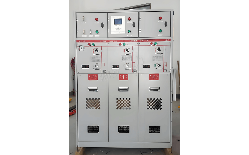
SF6 Fully Insulated Gas-Insulated Ring Main Units (hereinafter referred to as RMUs) primarily consist of load switch units and high-voltage AC load switch-fuse combination appliances (hereinafter referred to as combination appliances). Depending on user requirements, they can be configured as either common-tank or unitized structures.
In practical engineering applications, electrical connections are typically established using either top-mounted solid-insulated busbars or side-mounted plug-in busbars. Among the various technical parameters, the transfer current of the combination appliance unit and the closing capability of the load switch unit represent key challenges in development. Additionally, due to growing safety concerns, internal arc faults have increasingly drawn attention from users in recent years.
1. Analysis of Technical Issues
During the development and production of RMUs, the following aspects require careful consideration:
1.1 Transfer Current
The transfer current of a combination appliance refers to the three-phase symmetrical current at which the interrupting function transitions from the fuse to the load switch. For currents exceeding this value, interruption is performed exclusively by the fuses. Within lower fault current ranges, the melting times of the three-phase fuses exhibit inherent variability. The fuse with the shortest melting time interrupts first, and its striker activates, triggering the trip mechanism to open the load switch.
The interruption of the remaining two phases depends on a comparison between the actual time-current characteristics of their respective fuses (where the current in the remaining two phases is approximately 87% of the three-phase current) and the opening time of the load switch initiated by the striker of the first-interrupting fuse. If the fuse melting is delayed, the remaining two phases are interrupted by the load switch. Thus, fault current interruption in this range is shared between the fuse and the load switch.
The transfer current of the combination appliance is determined by two key factors: the tripping time of the load switch initiated by the fuse striker and the actual time-current characteristics of the fuse. The rated transfer current is a critical technical parameter, representing the maximum current the load switch can safely interrupt. When selecting current-limiting fuses, their time-current characteristics must be evaluated to ensure the resulting transfer current is below the rated transfer current of the combination appliance. This ensures reliable and safe coordination between the load switch and fuse, enabling effective protection of transformers.
1.2 Closing Capability
During load switch testing, unsuccessful closing operations occasionally occur, generally falling into two categories: failure to meet the required number of closing operations or inability to close at rated short-circuit currents. Analysis of test results indicates that such failures are predominantly caused by excessive erosion of the main contacts, which compromises their ability to carry the rated short-circuit current.
Therefore, minimizing or preventing main contact erosion is crucial to achieving successful test outcomes. Research and extensive testing have demonstrated that adding auxiliary contacts made of high-melting-point copper-chromium alloy to the original main contacts can indirectly protect the lower-melting-point copper main contacts. The specific design approach can be flexibly adapted based on the contact structure used—whether linear motion or rotary blade type.
2. Withstanding Internal Arc Faults
An electric arc reacts violently with surrounding air, causing rapid increases in temperature and pressure. If not properly contained, it can pose severe risks to personnel and equipment. Internal arc fault tests should be conducted separately for the gas compartment (switch compartment) and cable compartment of the RMU. To pass the test, the following criteria must be met:
Panels and doors of the switchgear must remain closed; limited deformation is acceptable.
The enclosure must not rupture, and no fragments heavier than 60 g may be ejected.
No holes may form on accessible surfaces of the switchgear up to a height of 2 m.
Horizontal and vertical indicators used during the test must not be ignited by hot gases.
The enclosure must remain connected to the grounding point throughout the test.
2.1 Rated Short-Circuit Breaking Current
The rated short-circuit breaking current of the combination appliance is determined by the selected fuse. The following considerations apply:
The fuse’s rated short-circuit breaking current must be greater than or equal to the maximum prospective fault current at the installation point in the distribution system.
The fuse’s rated short-circuit breaking current must be reasonably matched with the load switch’s rated short-time withstand current within the combination appliance.
Three fuses of the same model and specification must be installed; otherwise, interruption performance may be adversely affected.
Fuses must be correctly and fully installed to ensure the striker activates at the appropriate time and reliably triggers the load switch trip mechanism.
After one or two fuses operate, all three should be replaced unless it is certain that the unfused fuses did not carry current.
2.2 High-Altitude Operation
The design of sealed gas compartments in RMUs is typically based on operation at altitudes below 1,000 m. At higher altitudes, air becomes thinner and atmospheric pressure decreases. Since the internal gas density remains constant, the relative pressure within the sealed compartment increases. This can lead to increased mechanical stress on the enclosure, resulting in deformation and a higher risk of gas leakage. In such cases, the enclosure strength should be appropriately reinforced and validated through testing. Reducing the gas filling pressure (or density) is not a scientifically sound or recommended solution.
2.3 Moisture Content Control
Clause 6.5.1 of DL/T 791-2001, Guidelines for Selection of Indoor AC Gas-Insulated Switchgear, specifies moisture content in gas compartments: “When the rated filling pressure is no more than 0.05 MPa, moisture content shall not exceed 2,000 μL/L (by volume).” Other standards do not provide specific guidance. In RMU production, controlling moisture content at 1,000 μL/L (at 20°C) is considered reasonable, based on the following:
The load switch interrupts relatively small currents (630 A), with a maximum of transfer current (approximately 1,500–2,200 A).
The filling pressure is low (rated at 0.03–0.05 MPa), significantly lower than that of high-voltage GIS (around 0.5 MPa).
Sealing performance is excellent, resulting in very slow moisture ingress from the external environment.
Test results show minimal SF6 decomposition products after interruption.
During testing, samples were not deliberately moisture-controlled, yet no failures due to excessive moisture were observed.
Therefore, completely neglecting moisture control during production is unjustifiable, as is strictly adhering to insulation-based limits without considering arc-quenching requirements. Based on years of practical production and operational experience, maintaining moisture content at 1,000 μL/L (at 20°C) during manufacturing is both technically sound and reasonable.
3. Conclusion
RMUs have been manufactured and operated in China for many years, demonstrating mature technology, stable performance, and strong market acceptance. It is hoped that more manufacturers will enter this field and continue to explore, discuss, and share insights on technical challenges encountered in research, manufacturing, and operation, thereby collectively advancing RMU technology and promoting its continuous improvement.


