The Rise of Epoxy Dry Transformers in Modern Grids

The world's first transformer was developed in 1876. It featured a very simple design and used air as its insulation medium. In 1885, engineers in Hungary successfully built the first modern transformer with a closed magnetic circuit and air insulation, marking the beginning of rapid development and widespread application of transformers. Since then, the transformer industry has continuously advanced toward higher voltages and greater capacities.
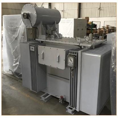
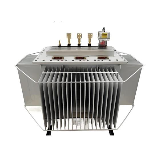
In 1912, the oil-immersed transformer was invented. It effectively addressed the challenges of high-voltage insulation and heat dissipation for large-capacity units, quickly becoming the dominant product in the transformer industry—a position it still holds today. The insulating medium in traditional oil-immersed transformers—mineral transformer oil—is crucial for both electrical insulation and cooling. However, it has inherent drawbacks: it is flammable and can even explode, requires regular maintenance and replacement, and poses environmental contamination risks if leaked.
As urban infrastructure expanded and safety standards rose, oil-immersed transformers became unsuitable for high-demand applications. This led to the emergence of epoxy resin-insulated dry-type transformers.

In 1965, Germany’s T.U. Company manufactured the first epoxy resin dry-type transformer, featuring aluminum windings encapsulated in an outer layer of epoxy resin. This innovation overcame the low dielectric strength that had plagued earlier air-insulated dry-type transformers.
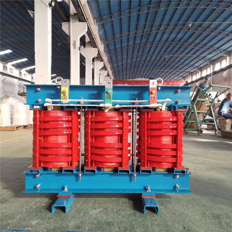
Epoxy resin is a non-flammable solid insulation material. Transformers using this technology offer high dielectric strength, fire safety (no risk of explosion), minimal maintenance, and environmental friendliness. These advantages drove their rapid adoption worldwide—particularly across Europe.
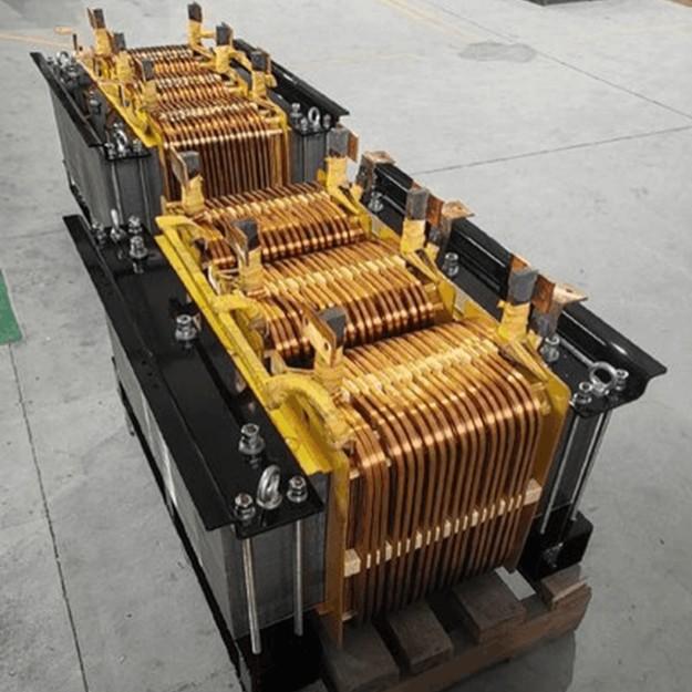
Within just three decades, epoxy resin dry-type transformers made significant progress in materials, design, and manufacturing processes, becoming a vital branch of the transformer family. Today, most such transformers use copper windings and are vacuum-cast with F- or H-class insulation-grade epoxy resin.
Continuous advancements have been achieved in reducing losses, lowering noise levels, enhancing reliability, and increasing single-unit capacity. Epoxy resin dry-type transformers are now widely used in urban buildings, transportation systems, energy facilities, chemical plants, and many other settings. To meet diverse technical requirements, they have further evolved into various types, including distribution transformers, power transformers, isolation transformers, rectifier transformers, electric furnace transformers, excitation transformers, and traction rectifier transformers.
China introduced epoxy resin dry-type transformer manufacturing technology in the 1970s, but development and application progressed slowly. It wasn’t until the late 1980s and early 1990s—driven by the import of advanced production technologies and rapid national economic growth—that dry-type transformers gained widespread adoption. Domestic manufacturers transitioned from technology assimilation to independent innovation, eventually reaching international advanced standards.
Today, China leads the world in dry-type transformer production volume, with numerous domestic manufacturers achieving global competitiveness in both product quality and R&D capabilities.
“Safer, cleaner, and more efficient” has become an essential part of modern life—and the emergence and evolution of epoxy resin dry-type transformers perfectly reflect this demand. Their ongoing development continues to align with society’s ever-rising expectations for safety, sustainability, and performance.