• Product
  • Suppliers
  • Manufacturers
  • Solutions
  • Free tools
  • Knowledges
  • Experts
  • Communities
Search


Transformer Bushings Guide: Functions, Structure, Types & Maintenance

Rockwell
Rockwell
Field: Manufacturing
China

1. Functions of Transformer Bushings

The core function of transformer bushings is to lead the coil leads out to the external environment. They serve both as insulating components between the leads and the oil tank and as fixing devices for the leads.

During the operation of a transformer, bushings continuously carry load currents and, in the event of an external short circuit, withstand short-circuit currents. Therefore, transformer bushings must meet the following requirements:

  • Possess specified electrical strength and sufficient mechanical strength;

  • Have good thermal stability to withstand instantaneous overheating during short circuits;

  • Feature a compact and lightweight structure, excellent sealing performance, strong versatility, and ease of maintenance.

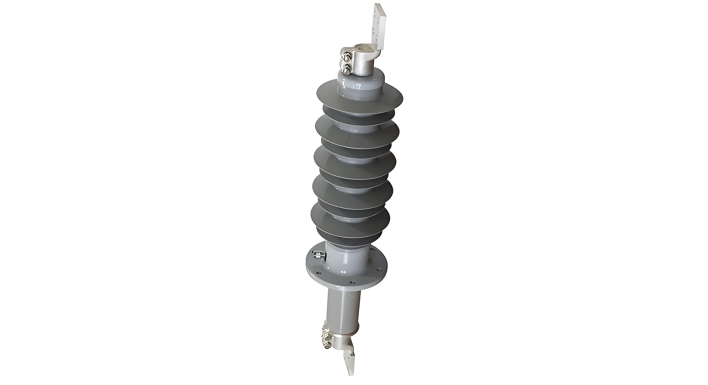
2. External Structure of Bushings

The external components of a bushing include: terminal boards, lead connectors, rain covers, oil level gauges, oil plugs, oil reservoirs, upper porcelain sleeves, lower shields, lifting rings, oil valves, nameplates, vent plugs, connecting bushings, lower porcelain sleeves, and equalizing balls.

3. Internal Structure of Bushings

  • Main Insulation Structure: Composed of a multi-layer cylindrical capacitor core, which is made of oil-impregnated cable paper and aluminum foil equalizing electrodes; the external insulation is provided by porcelain sleeves, which also act as containers for transformer oil.

  • Sealing Performance: Adopts a fully sealed structure, with the internal transformer oil forming an independent system that is not affected by external atmospheric conditions.

  • Connection Method: The overall connection uses strong spring mechanical fastening, ensuring both sealing performance and compensation for length expansion/contraction caused by temperature changes.

The oil reservoir at the top of the bushing is used to adjust the oil volume fluctuation caused by temperature changes, avoiding significant internal pressure variations; the oil level gauge on the oil reservoir can monitor the oil level in real-time during operation. The equalizing ball at the tail improves electric field distribution, shortening the insulation distance between the bushing tail and grounded components or coils.

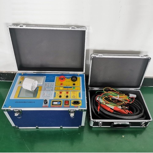
The small bushing on the end screen of oil-paper capacitor bushings can be used for capacitance, dielectric loss factor tests, and partial discharge tests of transformers. During normal operation, this small bushing must be reliably grounded. When disassembling the small bushing of the end screen, care must be taken to prevent rotation or pulling out of the small bushing rod, to avoid lead disconnection or damage to the copper foil on the electrode plate.

4. Arrangement of Three-Phase Transformer Bushings

When viewed from the high-voltage bushing side of the transformer, the left-to-right arrangement is labeled as follows:

  • High voltage side: O, A, B, C

  • Medium voltage side: Om, Am, Bm, Cm

  • Low voltage side: O, a, b, c

5. Classification of Bushings by Insulation Material and Structure

Bushings can be classified into three categories:

  • Single Insulation Bushings: Including pure porcelain bushings and resin bushings;

  • Composite Insulation Bushings: Further divided into oil-filled, gel-filled, and gas-filled bushings;

  • Capacitor Bushings: Including oil-paper capacitor bushings and resin-paper capacitor bushings.

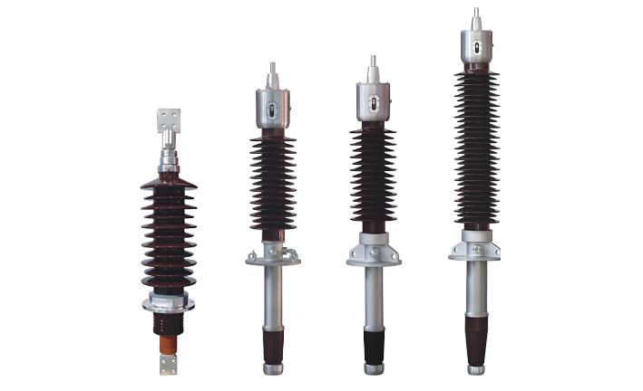
6. Oil-Paper Capacitor Bushings

According to the current-carrying structure, oil-paper capacitor bushings can be divided into cable-through type and conduit current-carrying type. Among them, the conduit current-carrying type is further classified into direct-connection type and rod-through type based on the connection method between the oil-side terminal and the bushing. Cable-through and direct-connection conduit current-carrying bushings are widely used in power systems, while rod-through oil-paper capacitor bushings are less common.

The manufacturing process of the capacitor core for capacitor bushings is as follows: Starting with a hollow conductive copper tube as the base, a layer of cable paper with a thickness of 0.08-0.12mm is first tightly wrapped as the insulation layer, followed by a layer of aluminum foil with a thickness of 0.01mm or 0.007mm as the capacitor shield; this alternating wrapping of cable paper and aluminum foil is repeated until the required number of layers and thickness are achieved.

This forms a multi-layer series capacitor circuit—where the conductive tube is at the highest potential, and the outermost aluminum foil is grounded (ground shield). According to the principle of series capacitor voltage division, the voltage between the conductive tube and the ground equals the sum of the voltages between each capacitor shield layer, and the voltage between shield layers is inversely proportional to their capacitance. This ensures that the total voltage is evenly distributed across the entire insulation layer of the capacitor core, achieving a compact and lightweight design for the bushing.

Give a tip and encourage the author!
Recommended
What Are Combined Transformer Standards? Key Specs & Tests
Combined Instrument Transformers: Technical Requirements and Testing Standards Explained with DataA combined instrument transformer integrates a voltage transformer (VT) and a current transformer (CT) into a single unit. Its design and performance are governed by comprehensive standards covering technical specifications, testing procedures, and operational reliability.1. Technical RequirementsRated Voltage:The primary rated voltages include 3kV, 6kV, 10kV, and 35kV, among others. The secondary v
Edwiin
10/23/2025
What Are the Types of Reactors? Key Roles in Power Systems
Reactor (Inductor): Definition and TypesA reactor, also known as an inductor, generates a magnetic field within the surrounding space when current flows through a conductor. Therefore, any current-carrying conductor inherently possesses inductance. However, the inductance of a straight conductor is small and produces a weak magnetic field. Practical reactors are constructed by winding the conductor into a solenoid shape, known as an air-core reactor. To further increase inductance, a ferromagnet
James
10/23/2025
35kV Distribution Line Single-Phase Ground Fault Handling
Distribution Lines: A Key Component of Power SystemsDistribution lines are a major component of power systems. On the same voltage-level busbar, multiple distribution lines (for input or output) are connected, each with numerous branches arranged radially and linked to distribution transformers. After being stepped down to low voltage by these transformers, electricity is supplied to a wide range of end users. In such distribution networks, faults such as phase-to-phase short circuits, overcurre
Encyclopedia
10/23/2025
Why Upgrade to Maintenance-Free Transformer Breathers?
Maintenance-Free Moisture Absorption Technology for Oil-Immersed TransformersIn traditional oil-filled transformers, the temperature control system causes thermal expansion and contraction of insulating oil, requiring the sealing gel chamber to absorb significant moisture from the air above the oil surface. The frequency of manual silica gel replacement during patrols directly impacts equipment safety—delayed replacement can easily lead to oil degradation. Maintenance-free moisture absorbers rev
Felix Spark
10/23/2025
Related Products
Send inquiry
Download
Get the IEE Business Application
Use the IEE-Business app to find equipment, obtain solutions, connect with experts, and participate in industry collaboration anytime, anywhere—fully supporting the development of your power projects and business.