• Product
  • Suppliers
  • Manufacturers
  • Solutions
  • Free tools
  • Knowledges
  • Experts
  • Communities
Search


Home Outlet Grounding Test: 3 Simple Methods

Oliver Watts
Oliver Watts
Field: Inspection and testing
China

Purpose of Grounding

  • System Functional Grounding (Working Grounding):In power systems, grounding is required for normal operation, such as neutral point grounding. This type of grounding is known as working grounding.

  • Protective Grounding:The metal enclosures of electrical equipment may become energized due to insulation failure. To prevent electric shock hazards to personnel, grounding is provided and is referred to as protective grounding.

  • Overvoltage Protection Grounding:Grounding is installed for overvoltage protection devices—such as lightning rods, surge arresters, and protective gaps—to eliminate the hazards of overvoltage (e.g., from lightning or switching surges). This is called overvoltage protection grounding.

  • Electrostatic Discharge (ESD) Grounding:For flammable oil, natural gas storage tanks, and pipelines, grounding is implemented to prevent hazards caused by static electricity accumulation. This is known as static grounding.

measure.jpg

Functions of Grounding

  • Prevent Electromagnetic Interference (EMI):Such as grounding digital equipment and shielding layers of RF cables to reduce electromagnetic coupling and noise.

  • Protect Against High Voltage and Lightning Surges:Grounding equipment racks and communication device enclosures prevents damage to equipment, instruments, and personnel from high voltage or lightning strikes.

  • Support Communication System Operation:For example, in submarine cable repeater systems, the remote power feed system uses a conductor-to-earth configuration, which requires reliable grounding.

Correct Selection of Grounding Resistance Measurement Methods and Principles

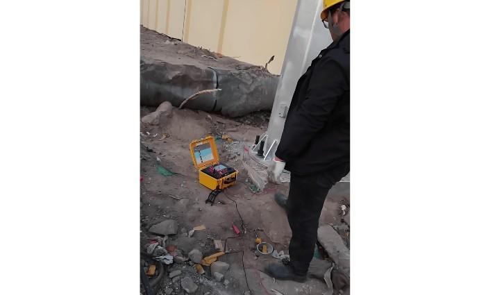
Several methods are commonly used to measure grounding resistance: 2-wire, 3-wire, 4-wire, single-clamp, and dual-clamp methods. Each has distinct characteristics. Selecting the appropriate method ensures accurate and reliable results.

(1) Two-Wire Method

  • Condition: Requires a known, well-grounded reference point (e.g., PEN conductor). The measured value is the sum of the tested ground resistance and the reference ground resistance. If the reference resistance is significantly smaller, the result approximates the tested ground resistance.

  • Application: Suitable for urban areas with dense buildings or sealed surfaces (e.g., concrete) where driving ground rods is impractical.

  • Wiring: Connect E+ES to the test point, and H+S to the known ground.

(2) Three-Wire Method

  • Condition: Requires two auxiliary electrodes: a current probe (H) and a voltage probe (S), each spaced at least 20 meters from the test electrode and from each other.

  • Principle: A test current is injected between the test electrode (E) and the auxiliary ground (H). The voltage drop between the test electrode and the voltage probe (S) is measured. The result includes the resistance of the test leads.

  • Application: Foundation grounding, construction site grounding, and lightning protection systems.

  • Wiring: Connect S to the voltage probe, H to the auxiliary ground, and E+ES together to the test point.

(3) Four-Wire Method

  • Description: Similar to the three-wire method but eliminates the influence of lead resistance by connecting E and ES separately and directly to the test point.

  • Advantage: Most accurate method, especially for low-resistance measurements.

  • Application: High-precision measurements in laboratories or critical grounding systems.

(4) Single-Clamp Method

  • Condition: Measures individual grounding points in a multi-grounded system without disconnecting the grounding connection (to avoid safety risks).

  • Application: Ideal for multi-point grounding systems where disconnection is not allowed.

  • Wiring: Use a current clamp to measure the current flowing through the grounding conductor.

(5) Dual-Clamp Method

  • Condition: Used in multi-grounded systems without requiring auxiliary ground rods. Measures the resistance of a single grounding point.

  • Wiring: Use manufacturer-specified current clamps connected to the instrument. Clamp both probes around the grounding conductor, with a minimum spacing of 0.25 meters between clamps.

  • Advantage: Fast, safe, and convenient for on-site testing in complex grounding networks.

How to Test Grounding in a Household Outlet

There are three simple methods:

Method 1: Resistance Test (Power Off)

  • Turn off the power.

  • Use a multimeter in resistance (Ω) or continuity mode.

  • Connect one end of a long wire to the ground terminal (C) of any outlet.

  • Connect the other end to one probe of the multimeter.

  • Touch the other probe to the main grounding busbar in your electrical panel.

  • If the multimeter shows continuity or a resistance ≤ 4 Ω, the grounding is normal.

Method 2: Voltage Test (Power On)

  • Use a multimeter in AC voltage mode.

  • For a standard 220V three-pin outlet, label:

    • A = Live (L)

    • B = Neutral (N)

    • C = Ground (PE)

  • Measure voltage between A and B (L-N).

  • Measure voltage between A and C (L-PE).

  • If the L-N voltage is slightly higher than L-PE (difference ≤ 5V), the grounding is likely normal.

  • Then switch to resistance or continuity mode and measure between B and C (N-PE).

    • If there is continuity or resistance ≤ 4 Ω, the grounding is normal.

Method 3: Direct Trip Test (Requires Functional RCD/GFCI)

  • Ensure the circuit is protected by a working residual current device (RCD) or ground fault circuit interrupter (GFCI).

  • Take a wire and briefly short the live (L) terminal to the ground (PE) terminal of the outlet.

  • If the RCD/GFCI trips immediately, the grounding system is functional and the protection mechanism is working correctly.

Give a tip and encourage the author!
Recommended
Complete Guide to Circuit Breaker Selection and Setting Calculation
How to Select and Set Circuit Breakers1. Types of Circuit Breakers1.1 Air Circuit Breaker (ACB)Also known as a molded frame or universal circuit breaker, all components are mounted within an insulated metal frame. It is typically open-type, allowing easy replacement of contacts and parts, and can be equipped with various accessories. ACBs are commonly used as main power supply switches. Overcurrent trip units include electromagnetic, electronic, and intelligent types. They provide four-stage pro
Echo
10/28/2025
Low-Voltage Distribution Cabinet Maintenance Steps and Safety Guide
Maintenance Procedure for Low-Voltage Power Distribution FacilitiesLow-voltage power distr ibution facilities refer to the infrastructure that delivers electrical power from a power supply room to end-user equipment, typically including distribution cabinets, cables, and wiring. To ensure the normal operation of these facilities and guarantee user safety and power supply quality, regular maintenance and servicing are essential. This article provides a detailed introduction to the maintenance pro
Edwiin
10/28/2025
Low-Voltage Electrical Work Safety Preparation and Operation Guide
Low-Voltage Electrician Safety Operating Procedures1. Safety Preparation Before performing any low-voltage electrical work, personnel must wear approved protective equipment, including insulating gloves, insulating boots, and insulating workwear. Carefully inspect all tools and equipment for proper operation. Report any damage or malfunction immediately for repair or replacement. Ensure adequate ventilation at the worksite. Avoid prolonged work in confined spaces to prevent fire hazards or poiso
Echo
10/28/2025
How to Handle Common Faults in RMU and Transformer Substations?
1. Ring Main Unit (RMU) and Transformer SubstationThe ring main unit (RMU) and transformer substation is a critical terminal in a distribution ring network system. The operational status of this terminal is directly affected by the performance of the distribution ring network system. Therefore, this section discusses the advantages, system composition, and key characteristics of the distribution ring network.1.1 Advantages of RMU and Transformer SubstationDue to technological limitations, radial
Felix Spark
10/28/2025
Send inquiry
Download
Get the IEE Business Application
Use the IEE-Business app to find equipment, obtain solutions, connect with experts, and participate in industry collaboration anytime, anywhere—fully supporting the development of your power projects and business.