Busbars and Connectors in HV and EHV installations

What is an Electric Busbar?
An electric busbar is a conductor or set of conductors designed to collect electrical power from incoming feeders and distribute it to outgoing feeders. Functionally, it serves as a junction where inflowing and outflowing currents converge, acting as a central hub for power aggregation and distribution.
Outdoor Busbar Installations
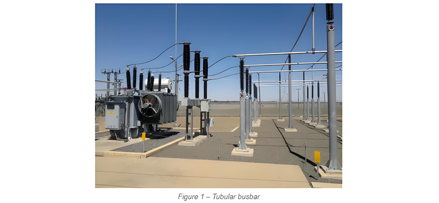
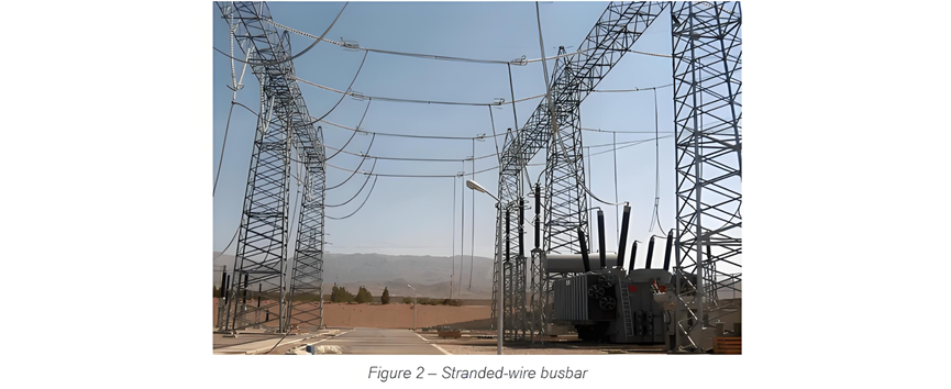
In high-voltage (HV), extra-high-voltage (EHV), and outdoor medium-voltage (MV) systems, bare busbars and connectors are typically used, with conductors available in tubular or stranded-wire configurations:
(Examples of the above configurations are illustrated in Figures 1 and 2.)
Busbars for Switchgear Installations
Switchgear busbars are typically fabricated from copper, aluminum, or aluminum alloys (e.g., Al-Mg-Si series), with key characteristics of bare busbars including:
Busbar Connection Technology
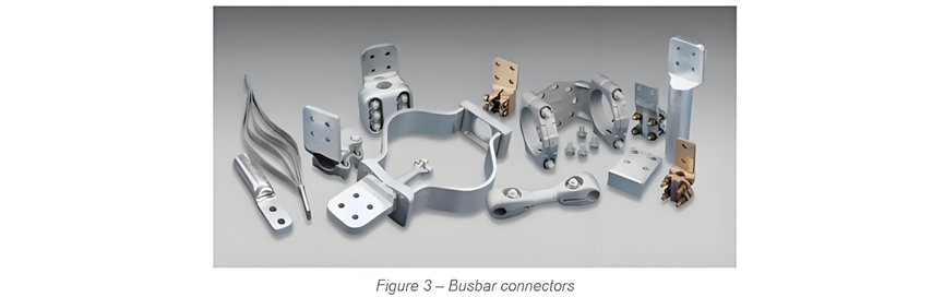
Dedicated connectors are essential for terminating busbars to equipment, as illustrated in Figure 3. Typical configurations include:
Connection design must comply with:
Engineering Considerations
Medium/high-voltage switchgear busbar systems require integrated design for:
These measures collectively ensure reliable power transmission and extended equipment service life.
Widely used in data centers and industrial plants for high-current power distribution, these systems enable flexible layout and easy expansion through modular design.
For copper-copper connections, bronze connectors are used; for aluminium-aluminium connections, aluminium alloy connectors should be applied; and for copper-aluminium connections, bi-metallic connectors are mandatory to prevent corrosion caused by electrolytic effects.
Insulated Busbars & Trunking Systems
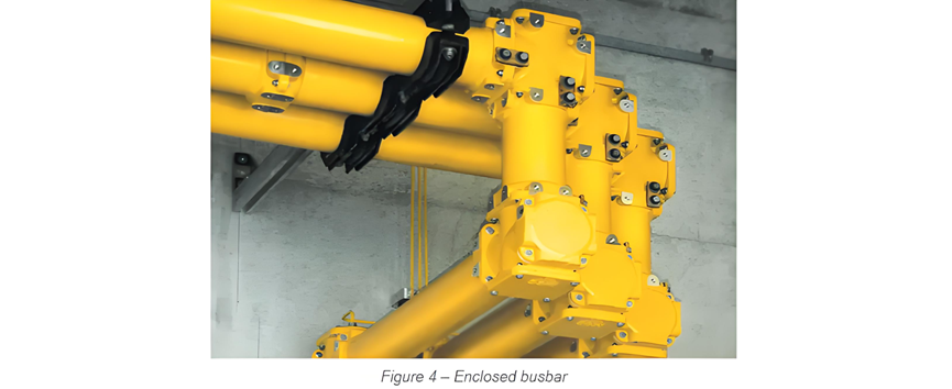
In indoor medium-voltage (MV) and low-voltage (LV) installations—particularly where high currents and limited space coexist—busbars are often enclosed in metallic casings for mechanical protection and insulation.This design reduces busbar heat dissipation due to restricted air flow and radiation losses, resulting in current ratings significantly lower than those for free-air installations. Ventilated enclosures can be used to minimize current derating.
Technical Details Analysis
Electrochemical Protection for Different Material Connections
Copper-copper joints: Bronze connectors (tin bronze or aluminium bronze) enhance contact reliability via solid solution strengthening, preventing pure copper creep relaxation.
Aluminium-aluminium joints: 6061-T6 aluminium alloy connectors undergo aging treatment to ensure oxide film stability.
Copper-aluminium transitions: Bi-metallic connectors use explosive welding or brazing (e.g., copper-aluminium composite bars) to block electrochemical corrosion paths.
Thermal Management Challenges in Enclosed Busbars
Thermal resistance analysis: Air gaps formed by enclosures reduce thermal conductivity by 30%-50%.
Compensation solutions:Forced air cooling: Internal fans increase current-carrying capacity by 20%-30%.
Enclosure cooling fins: Enhanced surface area for natural convection.
High thermal conductivity insulation: Silicone rubber coatings to reduce thermal resistance.
Engineering Application Specifications
Protection class: Typically IP54 for indoor environments, upgraded to IP65 in humid conditions.
Short-circuit withstand: Compliant with IEC 61439 dynamic and thermal stability requirements.
Expansion compensation: Expansion joints every 30-50 meters to accommodate thermal deformation.
Widely used in data centers and industrial plants for high-current power distribution, these systems enable flexible layout and easy expansion through modular design.
Isolated Busbars
Isolated busbars typically consist of copper or aluminium flat bars (one or more per phase, sized according to current requirements), with each phase enclosed in a separately earthed sheath. The sheath ends are connected by short-circuit rated bars capable of carrying full fault currents.The sheath primarily prevents inter-phase short circuits. Additionally, it cancels out magnetic fields generated by conductor currents: an equal and opposite current induced in the sheath neutralizes the electromagnetic field almost completely.Common insulating media include air and SF₆.
LV Busbar Trunking Systems
In low-voltage installations, busbar trunking systems offer a cost-effective solution for power distribution, supplying multiple devices and interconnecting switchboards or transformers, as shown in Figure 5.
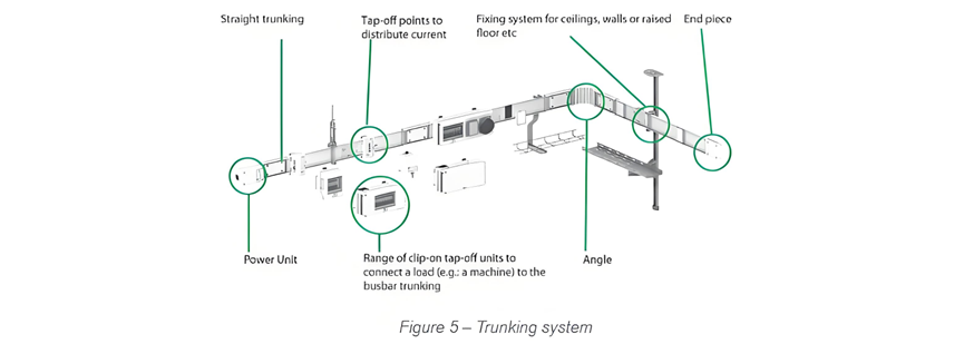
Busbar Trunking Systems
A busbar trunking system is a pre-assembled configuration housing flat-bar conductors (phase and neutral) within a single metallic enclosure.In feeder trunking systems, power tap-off is achieved via standardized tap-off units, which connect at predefined positions along the trunking. These units enable power extraction through compatible protective devices.
Advantages Over Cable Systems:


