1.Definition and Function
1.1 Role of the Generator Circuit Breaker
The Generator Circuit Breaker (GCB) is a controllable disconnect point located between the generator and the step-up transformer, serving as an interface between the generator and the power grid. Its primary functions include isolating generator-side faults and enabling operational control during generator synchronization and grid connection. The operating principle of a GCB is not significantly different from that of a standard circuit breaker; however, due to the high DC component present in generator fault currents, GCBs are required to operate extremely quickly to rapidly isolate faults.
1.2 Comparison Between Systems With and Without a Generator Circuit Breaker
Figure 1 illustrates the scenario of interrupting generator fault current in a system without a Generator Circuit Breaker.

Figure 2 shows the scenario of interrupting generator fault current in a system equipped with a Generator Circuit Breaker (GCB).

As illustrated in the comparison above, the advantages of installing a Generator Circuit Breaker (GCB) can be summarized as follows:
During normal startup and shutdown of the generating unit, auxiliary power supply switching is not required—only operation of the generator circuit breaker is needed, significantly enhancing the reliability of station service power.
In the event of an internal fault within the generator (i.e., on the generator side of the GCB), only the generator circuit breaker needs to be tripped, greatly reducing operational complexity during unit faults.
It provides better protection for the main transformer and high-voltage station service transformer. When an internal fault occurs in either of these transformers, the generator continues to feed fault current during the decay period of its field (excitation) current—even after the high-voltage side circuit breaker of the main transformer has been opened by protective relaying. With a GCB installed, the generator can be rapidly disconnected, thereby minimizing damage to the main transformer—a critical benefit for large generating units.
An additional significant advantage is the mitigation or elimination of damage to the generator caused by non-simultaneous (pole-disagreement) operation of the high-voltage circuit breaker. In generator-transformer unit connections, the high-voltage circuit breaker operates at a high rated voltage, and in open-type switchgear, the large phase-to-phase spacing prevents mechanical three-pole interlocking. Consequently, non-simultaneous operation can occur even during normal switching. Such conditions induce negative-sequence currents in the generator stator, and the rotor has very limited tolerance to negative-sequence magnetic fields—potentially leading to severe rotor damage. Modern GCBs, however, are designed and manufactured with three-phase mechanical interlocking, effectively preventing non-simultaneous operation.
For faults occurring on the generator side of the GCB, only the generator circuit breaker needs to be tripped—without opening the main transformer’s high-voltage side breaker—minimizing impact on the overall grid structure and benefiting system stability.
Power plant layout becomes simpler and more economical, reducing installation, commissioning time, and costs. The station service transformer and its associated medium- and high-voltage switchgear can be eliminated. With GCB implementation, average plant availability increases by 0.3%–0.6%, and higher generator availability translates directly into increased energy revenue.
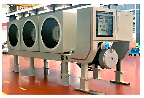
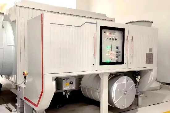
2. Structure and Function
2.1 Overall Structure
The circuit breaker system essentially consists of the following components and equipment, all mounted on a common support frame. Depending on the purchase order specifications, certain listed components may be excluded.
The standard design of the HEC/HECI-type switchgear includes:
SF₆ circuit breaker
Disconnector (isolating switch)
Earthing (grounding) switch
Capacitors
Current transformers (CTs)
Voltage transformers (VTs)
Surge arresters, shorting links, and the start-up switch (for Static Frequency Converter, SFC) are available as optional items.

1 – Circuit breaker 2 – Disconnector (Isolating switch) 3a – Earthing switch 3b – Earthing switch 4 – Shorting link 5 – Start-up switch (SFC) 6 – Capacitor
7 – Current transformer 8 – Voltage transformer 9 – Surge arrester 10 – Enclosure
The circuit breaker is filled with SF₆ gas as the arc-quenching medium. The main contacts and arcing contacts are separated. The contacts are operated by a spring-operated mechanism. The three poles of the circuit breaker are mechanically interlinked.

1 – Flexible connection 2 – Disconnector (Isolating switch) 3 – Arc extinguishing chamber 4 – Insulation 5 – Enclosure 6 – Earthing (Grounding) switch 7 – Isolated-phase busbar connection
8 – Current transformer
The internal components inside the GCB enclosure are shown in the figure below.

2.2 Component Composition and Function
1) Operating Mechanism
The HECI5-type GCB switch uses the AHMA 4 operating mechanism. The physical photo of this operating mechanism is as follows:

1 – Combined motor (oil pump motor) 2 – Control valve auxiliary contacts 3 – Auxiliary contacts
① Operating Module:
The module adopts a constant pressure differential structure, where high-pressure oil continuously acts on the upper end of the piston rod. The opening and closing speeds can be adjusted separately via corresponding throttle screws.
② Energy Storage Module:
Under the action of hydraulic oil, the accumulator piston compresses disc springs and stores hydraulic energy long-term in the energy storage piston cylinder, providing the necessary energy reserve for opening and closing operations.
③ Control Module:
Electrical command signals from the main control room activate the open/close solenoid valves, which in turn shift the directional control valve to achieve either opening or closing of the circuit breaker.
④ Adapter (Linkage) Module:
During piston rod movement, a connecting crank arm drives the auxiliary switch to rotate, thereby switching the open/close position signals.
⑤ Hydraulic Pump Module:
An electric motor drives the hydraulic pump to inject oil into the accumulator, converting electrical energy into hydraulic energy.
⑥ Monitoring Module:
The compression of the disc springs drives a cam on a limit switch, which rotates to open or close the contacts of a microswitch. This provides alarm signals and automatic interlocking functions for the main control room. (When the pressure exceeds the specified value, the pressure relief valve automatically opens to achieve overpressure protection.)
2) Circuit Breaker
The circuit breaker is the main component of the GCB. Its structural principle is not complex, and its functional schematic diagram is shown below:

S1 – Spring limit switch S0 – Auxiliary switch SA – Position indicator Y1 – Closing coil Y2, Y3 – Opening coils 1 and 2 M0 – Energy storage motor R10 – Heater DI – Density indicator
F6 – Density monitor
3) SF₆ Gas System
In the GCB, SF₆ gas is present only in the circuit breaker, the density relay, the density gauge, and the interconnecting gas piping.

The density monitor is a temperature-compensated pressure monitoring device used to monitor the SF₆ gas density in the three-pole (three-phase) circuit breaker. The gas pressure can be directly observed via the pressure gauge. When the pressure drops below a specified threshold, the density monitor sends a “REPLENISH GAS” signal. If the SF₆ pressure continues to decrease, two independent microswitches will activate interlocks that prevent any switching operations—the circuit breaker becomes mechanically and electrically locked out.
The set points of the density monitor are specified in the relevant control diagrams and the SF₆ gas density characteristic curves.
The control cabinet’s control panel consists primarily of four parts:
Interlock switch
Operation counter
Operation and alarm indicators
Local operation mode buttons
4) Control Cabinet
All functions of the circuit breaker’s operating mechanism are integrated within the control cabinet. The final configuration and functional layout are detailed in the relevant control diagrams. The following control components are all housed inside the control cabinet:
S2 – Local/Remote Selector Switch: The operating mode is selected via switch S2.
In the Remote position, commands can only be issued from the main control room.
In the Local position, commands can only be initiated from the circuit breaker’s control cabinet.
When in the Local position, the key of selector switch S2 cannot be removed. It is recommended to keep the key stored in the control room.
S11/S12 – Illuminated push-button switches for circuit breaker operation.
5) Pressure Relief (Explosion Protection) System
Bursting Disc: In the event of an internal arc fault (caused by prolonged short-circuit current), if the gas pressure inside the enclosure reaches the activation threshold, the bursting disc ruptures to release the excess pressure instantly. This rapid venting prevents catastrophic enclosure failure by safely discharging the overpressurized SF₆ gas.