What Key Aspects Matter for Combined Instrument Transformer Installation?

The installation quality of combined instrument transformers directly affects whether they can operate safely and stably. Therefore, during the installation process, several key aspects must not be overlooked — such as foundation construction, grounding, sealing checks, testing and commissioning, as well as secondary wiring. Below, I’ll explain these points in a more conversational way.
1. Foundation Construction Must Be Solid, Especially in Plateau Areas
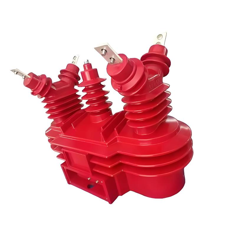
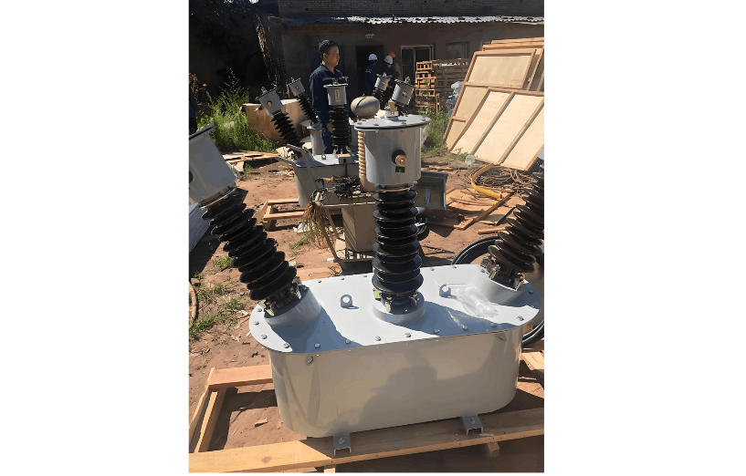
Although a combined instrument transformer may not look very big, it can actually be quite heavy — especially the oil-immersed types, which often weigh over 100 kg. So before installation, the base platform must be strong and level. Usually, we use channel steel to weld a sturdy base to ensure the transformer remains stable and doesn’t tilt or shake.
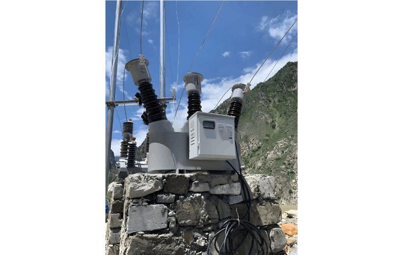
In plateau areas, where the climate and geology are special — like frozen ground, large temperature differences, and potential subsidence — the foundation construction needs extra attention to prevent settlement. The grounding grid density should be increased by about 50% compared to plains to ensure good grounding performance.
Also, some areas are earthquake-prone. For example, certain projects require the foundation to withstand seismic intensity of horizontal acceleration at 0.25g and vertical acceleration at 0.125g. In such cases, the foundation must be built to meet seismic requirements — no cutting corners allowed.
2. Grounding Cannot Be Ignored, Especially in Plateau Environments
Grounding may seem simple, but it’s extremely important — especially in plateau areas. The grounding resistance of the combined instrument transformer must be controlled below 5Ω. For the neutral point grounding of the secondary winding, the requirement is even stricter — the grounding resistance should be ≤1Ω to effectively prevent electromagnetic interference.To ensure reliable grounding, we usually use copper-aluminum transition clamps, and the clamps should be tinned to prevent oxidation and poor contact. When installing zero-sequence current transformers, pay special attention to their position:
If it’s installed above the cable sheath grounding lead, the grounding wire can be directly grounded.
If installed below, the grounding wire must pass through the primary winding of the CT before grounding, and this part of the wire must be insulated to avoid affecting the measurement or causing safety issues.
3. Sealing Inspection Is Critical in Plateau Installations
In plateau areas, with low air pressure and large temperature differences, the sealing performance of oil-immersed transformers is put to the test. After installation, carefully check whether the porcelain bushing and flange screws are tightened, whether the oil level is normal, and if there are any visible oil leaks.
For oil-immersed transformers, we usually perform a sealing test using pressure testing with air or nitrogen — dry air or nitrogen is injected into the conservator bag or onto the oil surface, and pressure is applied to detect leaks in the oil tank and components. This process must strictly follow national standards such as GB/T 6451 or GB/T 16274 to ensure there is no oil leakage.
For dry-type transformers, although there’s no oil involved, moisture and dust protection are still important. After installation, check whether the silicone rubber housing is intact, whether the seams are coated with RTV anti-tracking coating, and whether the protection level reaches at least IP55, so it can withstand the harsh plateau environment — such as strong winds and intense UV exposure.
4. Testing and Commissioning After Installation Cannot Be Skipped
After installation, don’t rush to put the transformer into operation — a few key tests must be done to ensure everything is in good condition:
Insulation resistance test: Insulation resistance between the primary winding and secondary winding and ground should be ≥1000MΩ; between secondary windings and ground should be ≥10MΩ.
Dielectric loss test (tanδ): This value should generally be controlled within 2%.
Volt-ampere characteristic test: Mainly to check whether the core is prone to saturation.
Polarity test: The polarity of the three-phase current transformers must be consistent; otherwise, the protection device may malfunction.
In particular, after installing a current transformer, the loop resistance must be measured to ensure there is no open circuit or parasitic circuit. For voltage transformers, an excitation curve test is also required. The test points are usually at 20%, 50%, 80%, 100%, and 120% of the rated voltage to ensure the excitation current is within the normal range.
5. Secondary Circuit Wiring Must Be Done Properly — Don’t Cut Corners
Although the secondary circuit operates at low voltage, incorrect wiring can have serious consequences. So during wiring, be especially careful:
The cross-sectional area of the secondary circuit wire for current transformers must be no less than 2.5mm².
For voltage transformers, the secondary circuit wire should be at least 1.5mm².
Unused secondary windings of current transformers must be shorted and grounded at the terminal block to prevent induced voltage from causing danger.
The secondary circuit of voltage transformers must be equipped with fuses for protection to prevent short circuits from damaging the equipment.
The secondary terminal block of the transformer should be installed on the maintenance side for easy inspection and maintenance in the future.
In short, the installation of a combined instrument transformer is not a small matter — especially in plateau environments, where extra attention must be paid. The base must be stable, the grounding must be solid, the sealing must be tight, the testing must be thorough, and the wiring must be accurate. Every step must be done carefully.
Only when all these details are handled properly can the instrument transformer operate safely and stably, providing accurate and reliable measurement and protection support for the power system.
I’m James, an “old electrician” who has been working in the instrument transformer industry for twelve years. I hope this experience sharing can help you. See you next time!