• Product
  • Suppliers
  • Manufacturers
  • Solutions
  • Free tools
  • Knowledges
  • Experts
  • Communities
Search


Front-Panel Visible Wiring Standards for Electrical Control Panels

James
James
Field: Electrical Operations
China

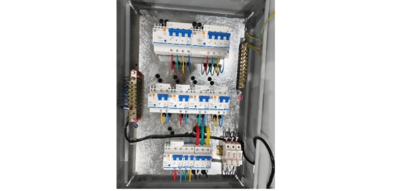
Front-panel visible wiring: During manual wiring (not using templates or molds), wiring must be straight, neat, closely attached to the mounting surface, rationally routed, and with secure connections that facilitate maintenance.

Visible Wiring Standards.jpg

  1. Wiring channels should be minimized as much as possible. Within the same channel, bottom-layer conductors shall be grouped by main and control circuits, arranged in a single-layer parallel dense layout or bundled, and kept closely attached to the mounting surface.

  2. Conductor length should be as short as possible. Horizontal aerial spans are permitted—for example, between two coil terminals or between main contact terminals—provided a certain amount of slack is left, and such conductors need not be tightly attached to the mounting surface.

  3. Conductors on the same plane shall be aligned at the same height or depth and must not cross. If crossing is unavoidable, a horizontal aerial span may be used, but only if it constitutes rational routing.

  4. Wiring must be horizontally level and vertically straight, with direction changes made at 90° angles.

  5. If upper and lower contact points are not vertically aligned, diagonal wiring shall not be used.

  6. When connecting conductors to terminal blocks or studs, the insulation layer must not be pinched, reverse loops are prohibited, and exposed copper shall not exceed 1 mm. Additionally, the spacing between conductors at different connection points of the same component or same circuit shall remain consistent.

  7. No more than two conductors shall be connected to a single terminal of an electrical component. Generally, only one conductor is allowed per terminal segment on a terminal block.

  8. During wiring, the conductor core and insulation must not be damaged.

  9. When conductors of different cross-sectional areas are used, those with larger cross-sections shall be placed in the lower layer, and those with smaller cross-sections in the upper layer.

  10. When routing multiple conductors (main power circuits), they shall be arranged so that the entire group lies on the same horizontal or vertical plane.

  11. Coding sleeves may be omitted if the wiring is simple.

Wire color coding:

  1. Protective earth (PE) conductors must be green-and-yellow.

  2. Neutral (N) and mid-point (M) conductors in power circuits must be light blue.

  3. AC or DC power circuits shall use black conductors.

  4. AC control circuits shall use red conductors.

  5. DC control circuits shall use blue conductors.

  6. Interlock conductors in control circuits that remain live when the external control circuit is disconnected shall be orange or yellow.

  7. Circuits connected to the protective conductor shall use white conductors.

Give a tip and encourage the author!
Recommended
How to Identify Internal Faults in a Transformer?
Measure DC resistance: Use a bridge to measure the DC resistance of each high- and low-voltage winding. Check whether the resistance values among phases are balanced and consistent with the manufacturer’s original data. If phase resistance cannot be measured directly, line resistance may be measured instead. The DC resistance values can indicate whether the windings are intact, whether there are short circuits or open circuits, and whether the contact resistance of the tap changer is normal. If
Felix Spark
11/04/2025
What are the requirements for inspecting and maintaining a transformer's no-load tap changer?
The tap changer operating handle shall be equipped with a protective cover. The flange at the handle shall be well sealed with no oil leakage. Locking screws shall securely fasten both the handle and the drive mechanism, and the handle rotation shall be smooth without binding. The position indicator on the handle shall be clear, accurate, and consistent with the tap voltage regulation range of the winding. Limit stops shall be provided at both extreme positions. The insulating cylinder of the t
Leon
11/04/2025
What Are the Common Inverter Fault Symptoms and Inspection Methods? A Complete Guide
Common inverter faults mainly include overcurrent, short circuit, ground fault, overvoltage, undervoltage, phase loss, overheating, overload, CPU malfunction, and communication errors. Modern inverters are equipped with comprehensive self-diagnostic, protection, and alarm functions. When any of these faults occurs, the inverter will immediately trigger an alarm or shut down automatically for protection, displaying a fault code or fault type. In most cases, the fault cause can be quickly identifi
Felix Spark
11/04/2025
What are the causes of dielectric withstand failure in vacuum circuit breakers?
Causes of Dielectric Withstand Failure in Vacuum Circuit Breakers: Surface contamination: The product must be thoroughly cleaned before dielectric withstand testing to remove any dirt or contaminants.Dielectric withstand tests for circuit breakers include both power-frequency withstand voltage and lightning impulse withstand voltage. These tests must be performed separately for phase-to-phase and pole-to-pole (across the vacuum interrupter) configurations.Circuit breakers are recommended to be t
Felix Spark
11/04/2025
Send inquiry
Download
Get the IEE Business Application
Use the IEE-Business app to find equipment, obtain solutions, connect with experts, and participate in industry collaboration anytime, anywhere—fully supporting the development of your power projects and business.