• Product
  • Suppliers
  • Manufacturers
  • Solutions
  • Free tools
  • Knowledges
  • Experts
  • Communities
Search


Tuned Collector Oscillator

Encyclopedia
Encyclopedia
Field: Encyclopedia
0
China

Tuned Collector Oscillator Definition


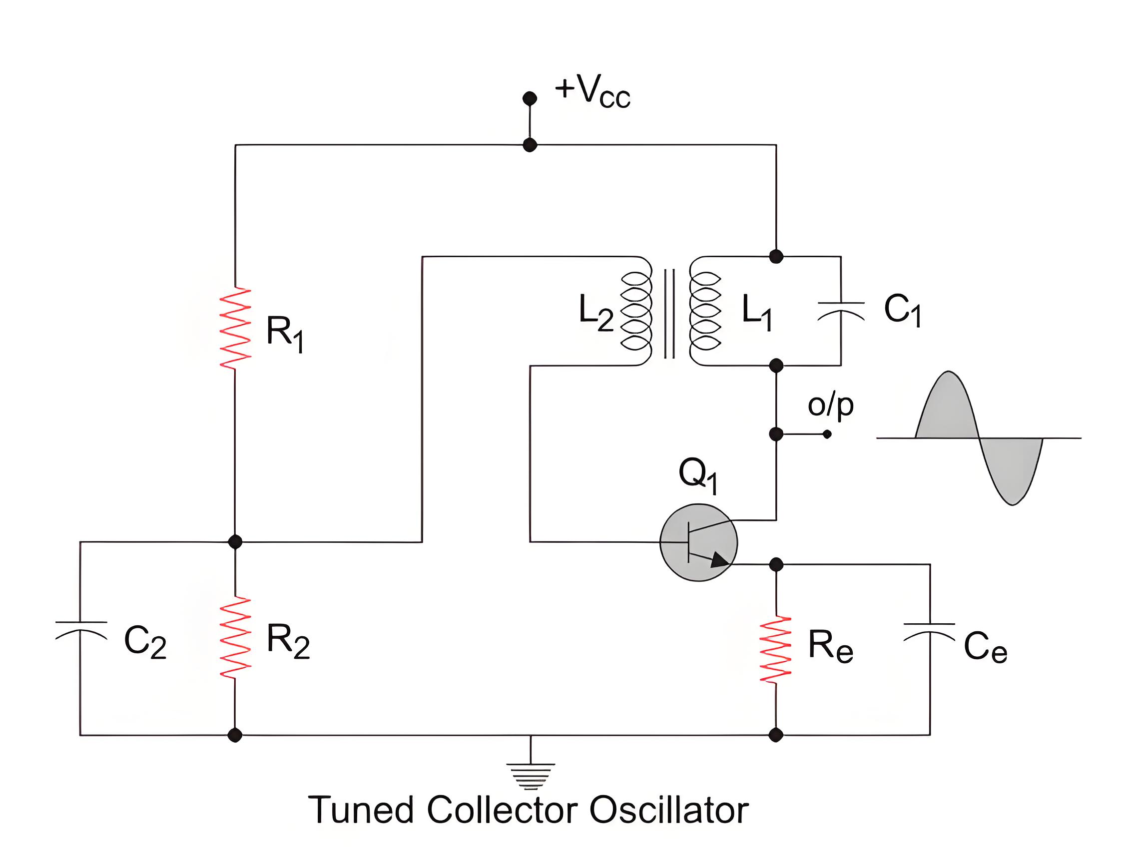
A tuned collector oscillator is defined as an LC oscillator that uses a tank circuit and a transistor to generate a periodic signal.


Circuit Diagram Explanation


56567440f5bf1518fd2a9c15833d6121.jpeg


The circuit diagram shows the tuned collector oscillator. The transformer and capacitor are connected to the transistor’s collector, producing a sine wave.


R1 and R2 form the voltage divider bias for the transistor. Re refers to the emitter resistor and is there to provide thermal stability. Ce is used to bypass the amplified ac oscillations and is the emitterbypass capacitor. C2 is the bypass capacitor for resistor R2. The primary of the transformer, L1 along with capacitor C1 forms the tank circuit.


Working of Tuned Collector Oscillator


Before we go into the working of the oscillator, let us just revise the fact that a transistor causes a phase shift of 180 degrees when it amplifies an input voltage. L1 and C1 form the tank circuit and it is from these two elements, we will get the oscillations. The transformer helps in giving a positive feedback(We will come back to this later) and the transistor amplifies the output. With that established, let us now proceed to understand the working of the circuit.


When the power supply is switched on, the capacitor C1 starts charging. When it is fully charged, it starts to discharge through the inductor L1. The energy stored in the capacitor in the form of electrostatic energy gets converted to electromagnetic energy and gets stored in the inductor L1. Once the capacitor discharges completely, the inductor starts charging the capacitor again. 


This is because inductors do not the current through them change quickly and hence it will change the polarity across itself and keep the current flowing in the same direction. The capacitor starts charging again and the cycle continues in this manner. The polarity across the inductor and capacitor changes periodically and hence we get an oscillating signal as the output.


Coil L2 charges through electromagnetic induction and sends this to the transistor. The transistor amplifies the signal, producing the output. A portion of this output is fed back into the system as positive feedback.


Positive feedback is the feedback which is in phase with the input. The transformer introduces a phase shift of 180 degrees and the transistor also introduces a phase shift of 180 degrees too. So in total, we get a 360-degree phase shift and this is fed back to the tank circuit. Positive feedback is necessary for sustained oscillations.


The frequency of oscillation depends on the value of the inductor and capacitor used in the tank circuit and is given by:


Where,

F = Frequency of the oscillation. L 1 = value of the inductance of primary of the transformer L1.C1 = value of capacitance of capacitor C1.


bb536373b37e9472008627391dc8d7cb.jpeg


Give a tip and encourage the author!
Recommended
What Are Combined Transformer Standards? Key Specs & Tests
Combined Instrument Transformers: Technical Requirements and Testing Standards Explained with DataA combined instrument transformer integrates a voltage transformer (VT) and a current transformer (CT) into a single unit. Its design and performance are governed by comprehensive standards covering technical specifications, testing procedures, and operational reliability.1. Technical RequirementsRated Voltage:The primary rated voltages include 3kV, 6kV, 10kV, and 35kV, among others. The secondary v
Edwiin
10/23/2025
MVDC: Future of Efficient, Sustainable Power Grids
The Global Energy Landscape Is Undergoing a Fundamental Transformation toward a "fully electrified society," characterized by widespread carbon-neutral energy and the electrification of industry, transportation, and residential loads.In today’s context of high copper prices, critical mineral conflicts, and congested AC power grids, Medium-Voltage Direct Current (MVDC) systems can overcome many limitations of traditional AC networks. MVDC significantly enhances transmission capacity and efficienc
Edwiin
10/21/2025
Grounding Causes of Cable Lines and the Principles of Incident Handling
Our 220 kV substation is located far from the urban center in a remote area, surrounded primarily by industrial zones such as Lanshan, Hebin, and Tasha Industrial Parks. Major high-load consumers in these zones—including silicon carbide, ferroalloy, and calcium carbide plants—account for approximately 83.87% of our bureau’s total load. The substation operates at voltage levels of 220 kV, 110 kV, and 35 kV.The 35 kV low-voltage side mainly supplies feeders to ferroalloy and silicon carbide plants
Felix Spark
10/21/2025
Overhead Power Lines & Towers: Types, Design & Safety
Besides ultra-high voltage AC substations, what we encounter more frequently are power transmission and distribution lines. Tall towers carry conductors that leap across mountains and seas, stretching into the distance before reaching cities and villages. This is also an interesting topic—today, let's explore transmission lines and their supporting towers.Power Transmission and DistributionFirst, let’s understand how electricity is delivered. The electric power industry primarily consists of fou
Encyclopedia
10/21/2025
Send inquiry
Download
Get the IEE Business Application
Use the IEE-Business app to find equipment, obtain solutions, connect with experts, and participate in industry collaboration anytime, anywhere—fully supporting the development of your power projects and business.