Analysis of Lightning Protection Measures for Distribution Transformers

Analysis of Lightning Protection Measures for Distribution Transformers
To prevent lightning surge intrusion and ensure the safe operation of distribution transformers, this paper presents applicable lightning protection measures that can effectively enhance their lightning withstand capability.
1. Lightning Protection Measures for Distribution Transformers
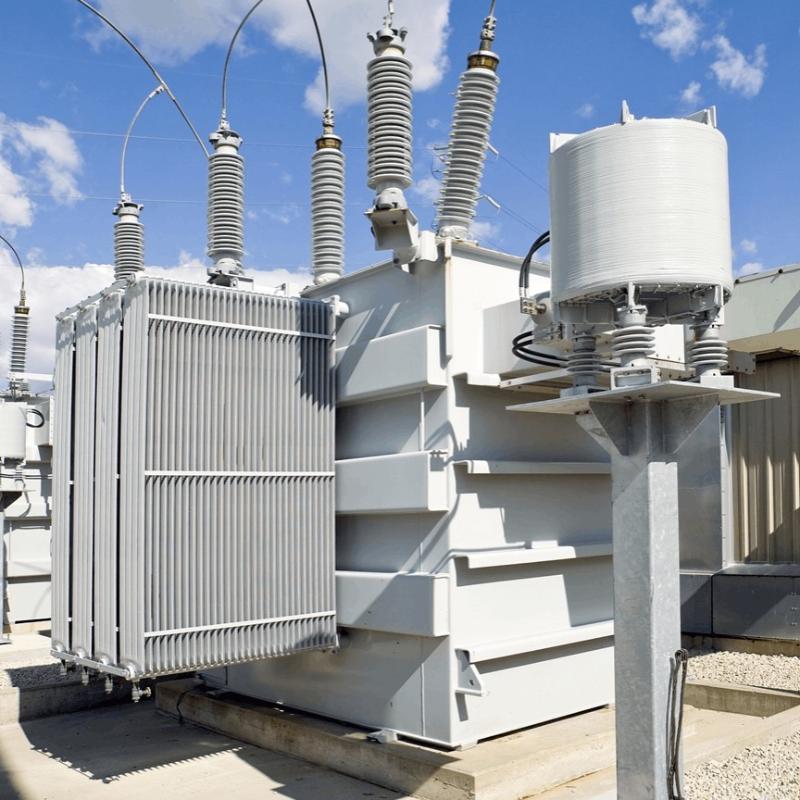
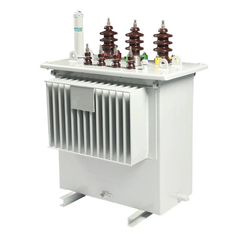
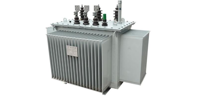
1.1 Install surge arresters on the high-voltage (HV) side of the distribution transformer.
According to SDJ7–79 Technical Code for Overvoltage Protection Design of Electric Power Equipment: “The HV side of a distribution transformer should generally be protected by surge arresters. The grounding conductor of the arrester, the neutral point of the low-voltage (LV) winding, and the transformer tank shall be bonded together and grounded.” This configuration is also recommended in DL/T620–1997 Overvoltage Protection and Insulation Coordination for AC Electrical Installations issued by China’s electric power authority.
However, extensive research and field experience show that even with HV-side arresters alone, transformer failures still occur under lightning surges. In typical areas, the annual failure rate is about 1%; in high-lightning regions, it can reach approximately 5%; and in extremely severe thunderstorm zones (e.g., areas with over 100 thunderstorm days per year), the annual failure rate may soar to around 50%. The primary cause is forward and reverse transient overvoltages induced when lightning surges invade the HV winding.
- Reverse Transformation Overvoltage:
When a lightning surge (3–10 kV) invades the HV side, the arrester discharges, causing a large impulse current to flow through the grounding resistance, creating a voltage drop. This voltage elevates the potential of the LV neutral point. If the LV line is long, it behaves like a wave impedance to ground. Consequently, a large impulse current flows through the LV winding. Since the three-phase LV currents are equal in magnitude and direction, they generate a strong zero-sequence magnetic flux, which—via transformer turns ratio—induces extremely high transient voltages in the HV winding. Because the HV winding is star-connected with an ungrounded neutral, no circulating impulse current exists in the HV side to counterbalance the flux. Thus, the entire LV impulse current acts as magnetizing current, producing high induced voltage at the HV neutral end—where insulation is most vulnerable. Additionally, inter-turn and inter-layer voltage gradients increase significantly, risking insulation breakdown elsewhere. This phenomenon—initiated by an HV-side surge but inducing overvoltage via LV electromagnetic coupling—is known as reverse transformation. - Forward Transformation Overvoltage:
When a lightning surge enters via the LV line, impulse current flows through the LV winding, inducing a high voltage in the HV winding through the turns ratio. This drastically raises the HV neutral potential and increases inter-layer and inter-turn voltage gradients. This process—where an LV-side surge induces overvoltage on the HV side—is called forward transformation. Tests show that with a 10 kV LV surge and a 5 Ω grounding resistance, the inter-layer voltage gradient in the HV winding can exceed the transformer’s full-wave impulse withstand strength by more than 100%, inevitably causing insulation failure.
1.2 Install conventional valve-type or metal oxide surge arresters on the LV side.
In this configuration, the grounding conductors of both HV and LV arresters, the LV neutral point, and the transformer tank are all bonded together and grounded (often referred to as “four-point bonding” or “three-in-one grounding”).
Field data and experimental studies confirm that even for transformers with good insulation, HV-side arresters alone cannot prevent damage from forward or reverse transformation overvoltages. HV arresters offer no protection against these internally generated transients. The resulting voltage gradients across layers and turns are proportional to the number of turns and depend on winding geometry—failures can occur at the winding start, middle, or end, with the terminal end being most vulnerable. Adding LV-side arresters effectively limits both forward and reverse transformation overvoltages.
1.3 Separate grounding for HV and LV sides.
In this approach, the HV arrester is grounded independently, while the LV neutral and transformer tank are bonded and grounded separately (without an LV arrester).
Research shows that this method leverages earth attenuation to largely eliminate reverse transformation overvoltage. For forward transformation, calculations indicate that reducing the LV grounding resistance from 10 Ω to 2.5 Ω can lower the HV-side overvoltage by approximately 40%. With proper treatment of the LV grounding system, forward transformation overvoltage can be effectively mitigated. This solution is simple and cost-effective, though it demands low LV grounding resistance, giving it considerable practical value.
Beyond the above, other measures include installing balancing windings on the transformer core to suppress transformation overvoltages or embedding metal oxide varistors (MOVs) inside the transformer.
2. Application of Lightning Protection Measures
The analysis above shows that each protection method has distinct characteristics. Regions should select appropriate strategies based on local thunderstorm intensity (measured in thunderstorm days per year):
- Low-lightning areas (e.g., plains):HV-side arrester alone is sufficient due to low annual failure rates.
- Moderate-lightning areas:Install arresters on both HV and LV sides.
- High-lightning areas:Single measures are often inadequate. A comprehensive approach is recommended: HV arrester with independent grounding, plus bonded LV arrester, LV neutral, and tank connected to a separate grounding system.
- Severe lightning zones (especially where annual failure rates remain high despite comprehensive measures):After technical and economic evaluation, consider advanced solutions such as core-mounted balancing windings (i.e., new-type lightning-resistant transformers) or internally installed metal oxide surge arresters.
3. Conclusion
Lightning protection methods for distribution transformers vary widely, and site conditions differ significantly across regions. By selecting protection schemes based on local conditions, and by strengthening operational management, utilities can substantially improve the lightning resilience and reliability of distribution transformers.