• Product
  • Suppliers
  • Manufacturers
  • Solutions
  • Free tools
  • Knowledges
  • Experts
  • Communities
Search


Parallel Magnetic Circuit

Edwiin
Edwiin
Field: Power switch
China

Definition of Parallel Magnetic Circuit

A parallel magnetic circuit is defined as a magnetic pathway with two or more branches for magnetic flux, analogous to a parallel electric circuit. Such circuits feature multiple flux paths with varying cross-sectional areas and materials, each potentially composed of different magnetic components.

Parallel Magnetic Circuit Analysis

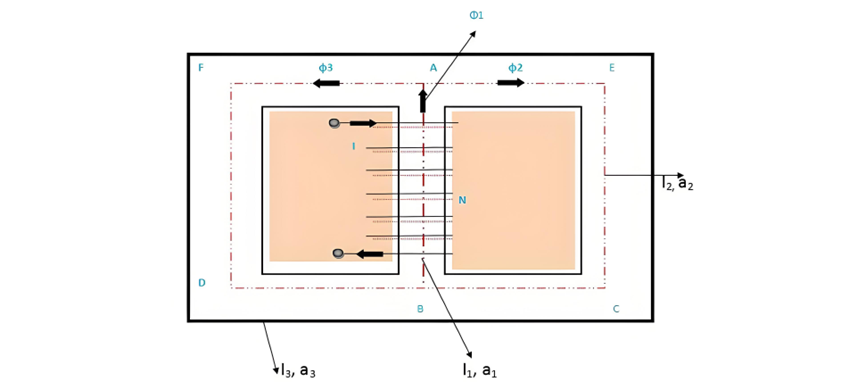
The figure above depicts a parallel magnetic circuit, where a current-carrying coil is wound around the central limb AB. This coil generates a magnetic flux φ₁ in the central limb, which travels upward and splits into two parallel paths: ADCB and AFEB. The path ADCB conducts flux φ₂, while AFEB carries flux φ₃. As evident from the circuit:

Parallel Magnetic Circuit Characteristics

The two magnetic paths ADCB and AFEB form a parallel magnetic circuit, where the ampere-turns (ATs) required for the entire parallel circuit equal the ampere-turns needed for any single branch.

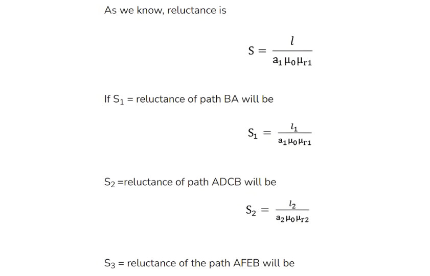
As is known, reluctance is defined as:

Parallel Magnetic Circuit MMF Calculation

Thus, the total magnetomotive force (MMF) or ampere-turns required for a parallel magnetic circuit equals the MMF of any single parallel path, as all branches experience the same applied MMF.

Incorrect Notation Clarification:

The total MMF is not the sum of individual paths (a common misconception). Instead, since parallel magnetic paths share the same applied MMF, the correct relation is:

Total MMF = MMF for path BA = MMF for path ADCB = MMF for path AFEB

Where φ1. Φ2, φ3 is the flux and S1, S2, S3 are the reluctances of the parallel path BA, ADCB and AFEB respectively.

Give a tip and encourage the author!
Recommended
Composition and Working Principle of Photovoltaic Power Generation Systems
Composition and Working Principle of Photovoltaic (PV) Power Generation SystemsA photovoltaic (PV) power generation system is primarily composed of PV modules, a controller, an inverter, batteries, and other accessories (batteries are not required for grid-connected systems). Based on whether it relies on the public power grid, PV systems are divided into off-grid and grid-connected types. Off-grid systems operate independently without relying on the utility grid. They are equipped with energy-s
Encyclopedia
10/09/2025
Transformer Use and Installation: Ensuring Safe and Reliable Operation
Operating Conditions for Transformers The installation site must be free from flooding, located at an altitude not exceeding 1,000 meters, and maintained in an ambient temperature not exceeding 40°C. Relative humidity may reach 100% within an operating temperature range of 40°C to -25°C (on-load tap changers and temperature controllers must be rated for -25°C). The installation area should be clean, free from conductive dust and corrosive gases, and equipped with sufficient natural or mechanical
Vziman
09/17/2025
 Advantages of SC Series Transformers: Advanced Production Equipment Enabling High Reliability
Advantages of SC Series Transformers: Advanced Production Equipment Enabling High Reliability
Heidrich Pouring Tank Features a fully integrated online film degassing system for enhanced resin quality. Employs static mixing technology—ensuring contamination-free processing with zero waste. Offers programmable mixing ratios and adjustable pouring speed for precise process control. Achieves an internal vacuum level of 0.8 to 2.5 bar, optimizing resin penetration and impregnation.Horizontal and Vertical Cutting Lines Delivers high-precision machining with a tolerance of ±0.01 mm and burr con
Rockwell
09/17/2025
Advantages of Dry-Type Transformers: Enhancing Safety and Environmental Performance
Compared to traditional oil-filled transformers, dry-type transformers offer several advantages. Key benefits of dry-type transformers include:Safety: Dry-type transformers are considered safer as they lack flammable liquid insulation (such as oil). They eliminate risks associated with oil leaks, spills, and related fire hazards. This makes them suitable for indoor installations, especially in areas where fire safety is a priority, such as commercial buildings, hospitals, and schools.Environment
Vziman
09/17/2025
Send inquiry
Download
Get the IEE Business Application
Use the IEE-Business app to find equipment, obtain solutions, connect with experts, and participate in industry collaboration anytime, anywhere—fully supporting the development of your power projects and business.