• Product
  • Suppliers
  • Manufacturers
  • Solutions
  • Free tools
  • Knowledges
  • Experts
  • Communities
Search


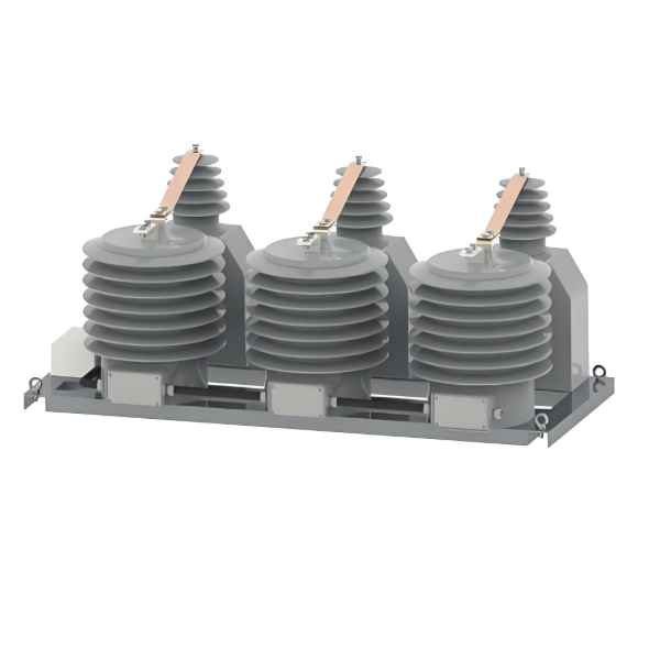
Combined Instrument Transformer (CIT) Solution: Engineering Design & Integration Perspective

Wone Store
2yrs + staff 1000+m² US$300,000,000+ China

1. Core Solution Concept: Modular Platform with Shared Insulation

  • Design:​ Develop a unified, modular platform housing both current and voltage sensing functions within a single, optimized structure.
  • Insulation:​ Utilize a shared insulating envelope. Two options are engineered:
    • SF6 Gas:​ Proven high-dielectric strength and excellent arc-quenching properties for higher voltage classes (e.g., 72.5 kV and above). Design incorporates gas density monitoring and proven sealing technology.
    • Composite Housing (Solid Insulation):​ Environmentally sustainable solution using high-grade polymer materials with silicone sheds. Ideal for lower to medium voltages or where SF6 avoidance is mandated. Optimized for creepage distance and pollution performance.
  • Modularity:​ Design internal components and interfaces to allow for:
    • Scalability across different voltage classes (e.g., through insulator length adjustment).
    • Adaptation to specific bushing interface requirements.
    • Potential for future sensor technology upgrades.

2. Integrated Sensing Technology Implementation

  • Current Measurement:
    • Sensor:​ High-accuracy, temperature-compensated Rogowski coils. Selected for:
      • Wide Dynamic Range:​ Excellent linearity from small fractions of nominal current up to high fault currents (e.g., >40 kA).
      • No Saturation:​ Fundamental advantage over iron-core CTs, eliminating saturation risk during faults.
      • Lightweight:​ Significantly reduces mechanical stress on the overall structure.
    • Integration:​ Coils strategically placed within the insulator envelope, concentric with the primary conductor. Secure mechanical mounting resistant to vibration.
  • Voltage Measurement:
    • Sensor:​ High-stability capacitive voltage dividers (CVDs) as standard. Resistive dividers (RVDs) considered for specific DC or wide-bandwidth applications requiring fast transient response.
    • Integration:​ CVD sensing electrodes (low-impedance) integrated directly into the insulator structure. Precision grading electrodes ensure uniform field distribution and thermal/pollution stability. Critical shielding prevents external field interference.

3. Advanced Electromagnetic Field Modeling & Isolation (Critical Engineering Challenge)

  • Modeling:​ Mandatory, high-fidelity 3D Finite Element Method (FEM) modeling of the entire platform:
    • Precisely characterizes internal electromagnetic fields under all operational conditions (sinusoidal, transient, distorted waveforms).
    • Evaluates proximity effects from conductors, enclosure, and adjacent phases.
  • Minimizing Crosstalk:
    • Physical Separation:​ Optimal geometric arrangement of sensing elements (coils, CVD electrodes) based on modeling results. Maximize distance within constraints.
    • Active Shielding:​ Implementation of grounded electrostatic shields strategically placed between sensor elements based on field simulation data.
    • Guard Rings:​ Utilize conductive guard rings around Rogowski coil outputs to drain displacement currents.
  • Precise Measurement Isolation:
    • Dedicated Signal Paths:​ Routing signals from individual sensors using shielded, twisted-pair cabling within the enclosure immediately upon capture.
    • Compensated Circuit Design:​ Electronic conditioning circuits designed with crosstalk cancellation techniques informed by FEM models.
    • Validation:​ Rigorous factory testing (including harmonic injection tests) to characterize and verify isolation margins and crosstalk levels (< 0.1% specified).

4. Integrated Digital Processing & Standardized Interfaces

  • Onboard Signal Processing:
    • Dedicated, low-power ASICs or high-reliability microcontrollers directly integrated onto the sensor platform or adjacent sealed module.
    • Functions include: Rogowski coil integrator, scaling, ADC conversion, harmonic computation (if applicable), linearization, temperature compensation, and timestamping.
  • Standardized Digital Output:
    • Embedded Interfaces:​ Incorporate IEC 61869 compliant digital output circuitry directly within the CIT unit.
    • Protocols:​ Standardized support for:
      • IEC 61850-9-2:​ Sampled Values (SV) stream over Ethernet (typically multicast).
      • IEC 61850-9-3LE:​ Lightning Edition SV profile for guaranteed low-latency determinism.
    • Additional Options:​ Provision for legacy outputs (analog, IEC 60044-8 FT3) where required via optional modules.
  • Data Quality:​ Integrated Merging Unit (MU) functionality meeting relevant IEC 61869 accuracy (TPE/TPM class) and timing (PLL synchronization) standards.

5. Engineering Design & Integration Considerations

  • Thermal Management:​ Models include thermal performance analysis. Power dissipation from electronics actively managed using low-power components, potential localized heatsinks, and optimized convection paths within the insulator.
  • EMC/EMI Robustness:​ Conformal coating, shielded enclosures, ferrites, and optimized grounding strategies applied to internal electronics. Surge protection compliant with relevant standards (IEC 61000-4-5).
  • Mechanical Integrity:​ Structural analysis performed for seismic loads, wind loading, ice loading, and dynamic forces during faults. Optimized use of materials (composite/porcelain/SF6) contributes to lower seismic mass.
  • Factory Calibration & Testing:​ Comprehensive calibration against reference standards (optical/VTBI methods). Includes verification of EM isolation effectiveness, timing accuracy, protocol compliance, and full-power dielectric testing.
  • Lifecycle & Serviceability:​ Designed for minimal maintenance (especially SF6 or solid insulation). Modular electronics potentially accessible/testable without major disassembly. End-of-life disposal pathways considered (SF6 recovery/recycling).

Benefits Realized through this Design & Integration Approach:

  • Footprint Reduction:​ Up to 40-50% space savings vs. separate CTs/VTs – crucial for retrofits and compact GIS/AIS designs.
  • Enhanced Accuracy & Safety:​ Eliminates traditional CT saturation risks, improves transient response (Rogowski/CVD), reduces external connections/risks.
  • Simplified Installation:​ Single unit mounting and commissioning significantly reduce field labor and cabling complexity.
  • Lower Lifecycle Costs:​ Reduced installation, cabling, civil work, maintenance overhead.
  • Digital Substation Readiness:​ Direct IEC 61850-9-2/3LE output enables seamless integration into modern protection, control, and monitoring systems (SAS).
  • Future-Proof Platform:​ Modular design accommodates evolving sensor technologies and communication standards.
  • Reduced Environmental Impact (Solid Insulation Option):​ Eliminates SF6 usage and associated risks.
07/22/2025
Recommended
Solution for Medium-Voltage Motor Control and Protection Using Vacuum Contactor-Fuse (VCF) in a Coal Conveying System
Project BackgroundA coal conveying system comprises 15 belt conveyors driven by medium-voltage motors. The system operates under complex conditions, with motors often subjected to heavy loads and frequent starts. To address these challenges and achieve effective control and reliable protection during motor startup, the project comprehensively adopts Vacuum Contactor-Fuse (VCF) combination devices for the 6kV medium-voltage motor power distribution. This solution details the technical features,
ABB Vacuum Contactor KC2 Power Supply System Technical Transformation Plan
Issue Overview​The 10kV air compressor starting system of a company utilizes the ABB vacuum contactor KC2 as the control component for the operating circuit. The dedicated wide-voltage power supply module paired with this contactor presents the following issues:​Frequent failures: The power supply module fails to properly transition the voltage from 300V to 12V, resulting in fuse blowouts.​Poor heat dissipation: Enclosed installation of the module leads to insufficient heat dissipation, acceler
Dedicated Vacuum Contactor Solution for Port Shore Power Systems
I. Background and Challenges​Shore power systems have become core technical equipment for ports to reduce carbon emissions and noise pollution. However, these systems face two major challenges in the harsh operational environment of ports:​Severe Environmental Corrosion: High humidity and salt spray in port areas cause serious corrosion to metal components and enclosures of electrical equipment, significantly impacting electrical lifespan and operational reliability.​High Switching Requirements:
Vacuum Contactor Industrial Power Control Solutions
Application Background and Pain Point Analysis​In modern industrial manufacturing power control systems, traditional contactors exhibit significant limitations under specific operating conditions:• ​Frequent Start-Stop Operations: Traditional contactors have limited mechanical lifespan, with frequent operations leading to coil burnout and mechanical jamming.• ​Poor Adaptability to Harsh Environments: Contacts are prone to oxidation in dusty environments, resulting in increased contact
Seed Inquiry
Download
Get the IEE Business Application
Use the IEE-Business app to find equipment, obtain solutions, connect with experts, and participate in industry collaboration anytime, anywhere—fully supporting the development of your power projects and business.