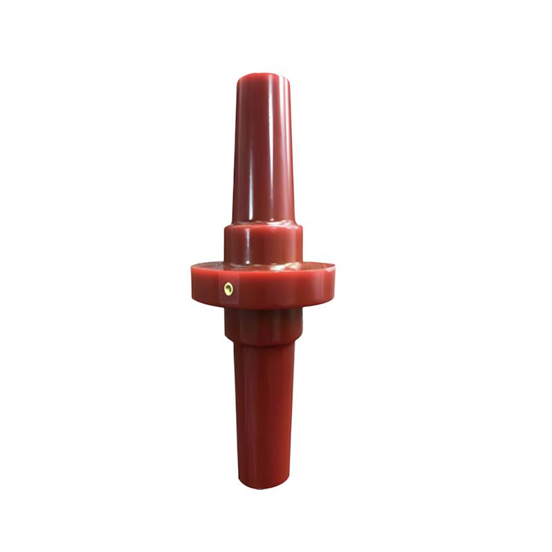
• Product
  • Suppliers
  • Manufacturers
  • Solutions
  • Free tools
  • Knowledges
  • Experts
  • Communities
Search


Special Side-Expanding Bushing for Solid Insulated Switchgear

  • Special Side-Expanding Bushing for Solid Insulated Switchgear
  • Special Side-Expanding Bushing for Solid Insulated Switchgear

Key attributes

Brand Switchgear parts
Model NO. Special Side-Expanding Bushing for Solid Insulated Switchgear
Rated voltage 12kV
Rated normal current 630A
Series RNCK

Product descriptions from the supplier

Description

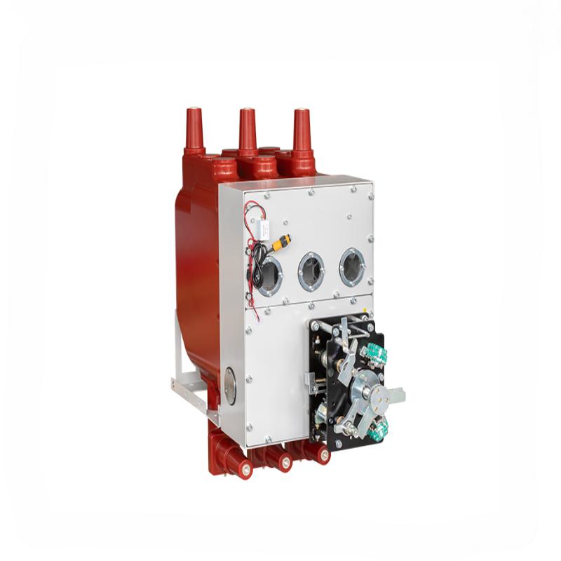
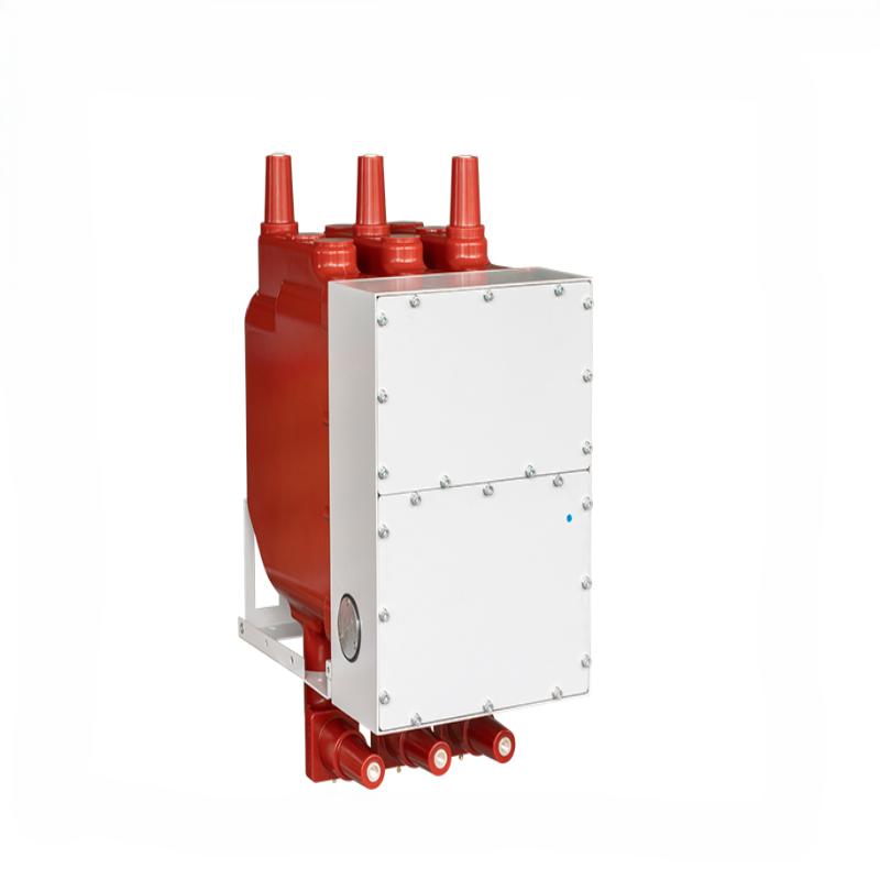
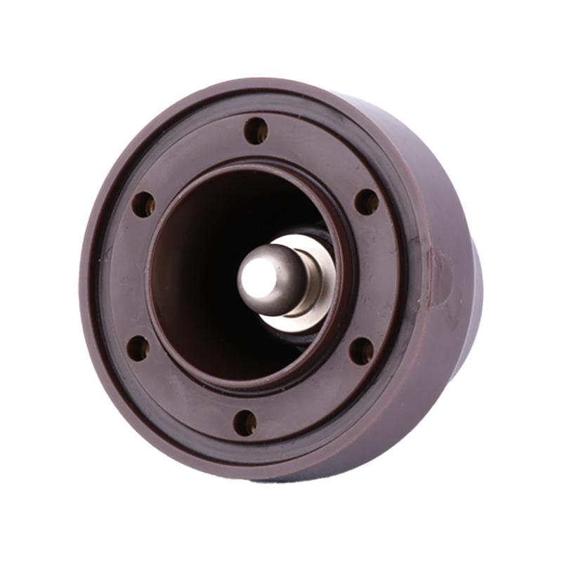
Side width is a critical component of solid insulated cabinets, specifically referring to the width of the cabinet's side, suitable for 12kV/24kV medium voltage distribution scenarios.
Core Features
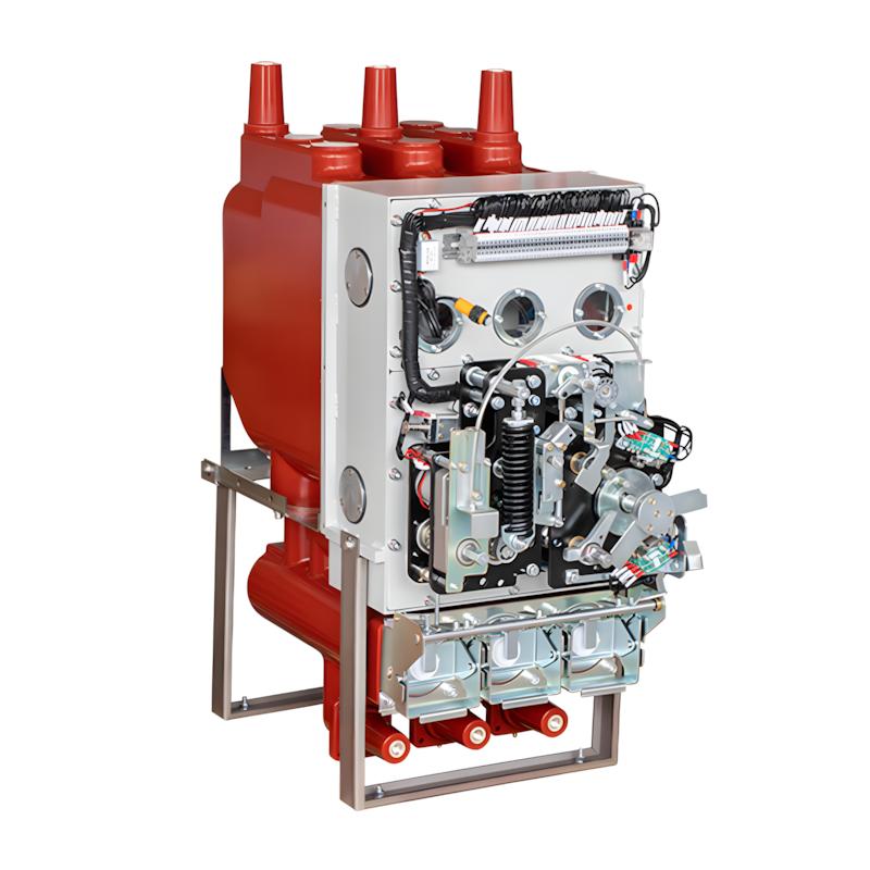
Accurately matching the overall structure of the solid insulation cabinet to ensure installation compatibility with other components.
Based on the insulation design requirements of the cabinet, taking into account the utilization of installation space and insulation protection performance, it is suitable for scenarios such as power distribution rooms and industrial plants.

Precautions for side width installation of solid insulation cabinet

1、 Size adaptation verification
Before installation, confirm that the actual dimensions of the side width are consistent with the cabinet design drawings, and the deviation should be controlled within ± 2mm to avoid interference with adjacent components such as busbars and sleeves.
Check the compatibility between the side width and the installation foundation (such as brackets and guide rails) to ensure that the support points are fully aligned with the side width stress surface and there is no hanging situation.
2、 Insulation protection guarantee
The installation surface of the side width should be kept clean and dry, free of impurities such as oil stains and metal debris, to prevent affecting the overall insulation performance of the cabinet.
During installation, avoid scratching the insulation coating on the side wide surface. If there is any damage, it should be repaired promptly with specialized insulation materials that comply with relevant IEC insulation standards.
3、 Space and layout requirements
A maintenance space of ≥ 10cm should be reserved on both sides of the side width, taking into account subsequent maintenance and heat dissipation, and avoiding close contact with walls or other equipment.
When multiple cabinets are installed in parallel, the standard for side width dimensions should be unified to ensure that the cabinets are arranged neatly and the spacing between adjacent cabinets is even, without affecting switch operation and circuit connection.
4、 Fixed and stress specifications
Special fasteners are used to fix the side width, and the tightening torque meets the requirements of the product manual (usually 8-12N · m) to avoid component deformation caused by over tightening.
After installation, check the verticality of the side width, with a deviation of ≤ 3 ‰, to prevent long-term uneven stress from affecting the stability of the cabinet structure.
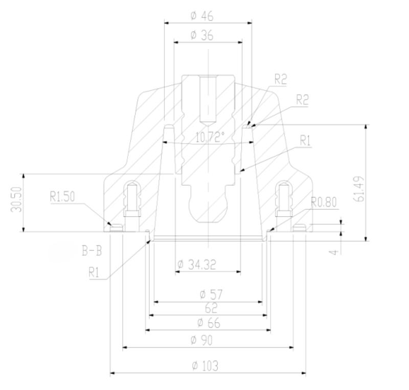
Overall dimensions

FAQ
Q: What safety precautions should be taken when using this side-expanding bushing?
A:

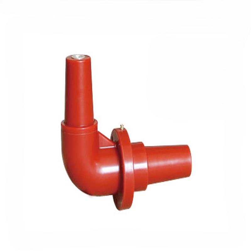
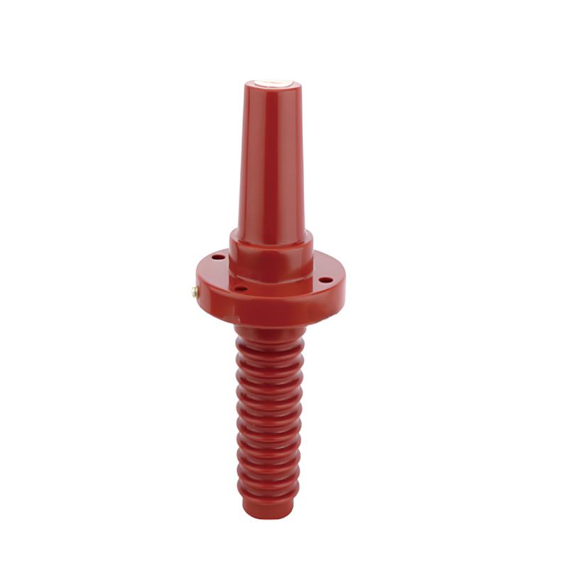
Key precautions to avoid electrical hazards: ① Power-off operation: Cut off the power supply and implement lockout-tagout before installation, maintenance or replacement; ② Protective equipment: Wear insulated gloves and insulated shoes during operation, do not touch live parts; ③ Avoid overload: Do not exceed the rated current and voltage to prevent insulation breakdown and overheating; ④ Transportation protection: Use shockproof packaging to avoid collision and extrusion damage to the bushing; ⑤ Regular inspection: Strengthen inspections in vibration-prone environments to prevent connection loosening and arcing....

Q: What are the core functions and working principles?
A:

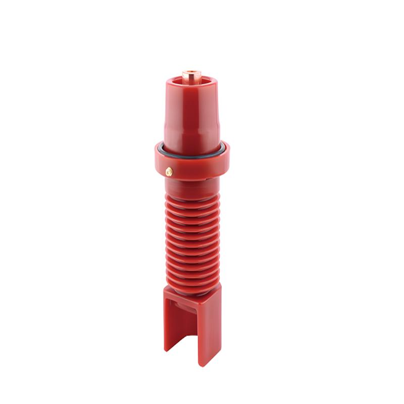
 It is a specialized insulation accessory for solid insulated switchgear (SIS) and ring main units (RMU). Core functions: ① Lateral conductor connection and insulation isolation between internal and external components of the switchgear; ② Side-expanding structure adapts to narrow installation spaces, optimizing the layout of the switchgear cabinet; ③ Preventing leakage current and pollution flashover. Working principle: Adopt high-strength epoxy resin APG casting process, the side-expanding structure increases creepage distance; the embedded metal conductor realizes current transmission, and the solid insulation layer blocks high-voltage breakdown, fully matching the SF6-free design of SIS.

Know your supplier
Online store
On-time delivery rate
Response time
100.0%
≤4h
Company overview
Workplace: 1000m² Total staff: Highest Annual Export(usD): 300000000
Workplace: 1000m²
Total staff:
Highest Annual Export(usD): 300000000
Services
Business Type: Sales
Main Categories: Low Voltage Electrical Apparatus/Instrument meters/Production equipment/Tester/High Voltage Electrical Apparatus/Electrical fittings/Equipment Parts
Whole life care manager
Whole-life care management services for equipment procurement, use, maintenance, and after-sales, ensuring safe operation of electrical equipment, continuous control, and worry-free electricity consumption.
The equipment supplier has passed platform qualification certification and technical evaluation, ensuring compliance, professionalism, and reliability from the source.

Related Products

Related Knowledges

  • Impact of DC Bias in Transformers at Renewable Energy Stations Near UHVDC Grounding Electrodes
    Impact of DC Bias in Transformers at Renewable Energy Stations Near UHVDC Grounding ElectrodesWhen the grounding electrode of an Ultra-High-Voltage Direct Current (UHVDC) transmission system is located close to a renewable energy power station, the return current flowing through the earth can cause a rise in ground potential around the electrode area. This ground potential rise leads to a shift in the neutral-point potential of nearby power transformers, inducing DC bias (or DC offset) in their
    01/15/2026
  • HECI GCB for Generators – Fast SF6 Circuit Breaker
    1.Definition and Function1.1 Role of the Generator Circuit BreakerThe Generator Circuit Breaker (GCB) is a controllable disconnect point located between the generator and the step-up transformer, serving as an interface between the generator and the power grid. Its primary functions include isolating generator-side faults and enabling operational control during generator synchronization and grid connection. The operating principle of a GCB is not significantly different from that of a standard c
    01/06/2026
  • Distribution Equipment Transformer Testing, Inspection, and Maintenance
    1.Transformer Maintenance and Inspection Open the low-voltage (LV) circuit breaker of the transformer under maintenance, remove the control power fuse, and hang a “Do Not Close” warning sign on the switch handle. Open the high-voltage (HV) circuit breaker of the transformer under maintenance, close the grounding switch, fully discharge the transformer, lock the HV switchgear, and hang a “Do Not Close” warning sign on the switch handle. For dry-type transformer maintenance: first clean the porcel
    12/25/2025
  • How to Test Insulation Resistance of Distribution Transformers
    In practical work, insulation resistance of distribution transformers is generally measured twice: the insulation resistance between thehigh-voltage (HV) windingand thelow-voltage (LV) winding plus the transformer tank, and the insulation resistance between theLV windingand theHV winding plus the transformer tank.If both measurements yield acceptable values, it indicates that the insulation among the HV winding, LV winding, and transformer tank is qualified. If either measurement fails, pairwise
    12/25/2025
  • Design Principles for Pole-Mounted Distribution Transformers
    Design Principles for Pole-Mounted Distribution Transformers(1) Location and Layout PrinciplesPole-mounted transformer platforms should be located near the load center or close to critical loads, following the principle of “small capacity, multiple locations” to facilitate equipment replacement and maintenance. For residential power supply, three-phase transformers may be installed nearby based on current demand and future growth projections.(2) Capacity Selection for Three-Phase Pole-Mounted Tr
    12/25/2025
  • Transformer Noise Control Solutions for Different Installations
    1.Noise Mitigation for Ground-Level Independent Transformer RoomsMitigation Strategy:First, conduct a power-off inspection and maintenance of the transformer, including replacing aged insulating oil, checking and tightening all fasteners, and cleaning dust from the unit.Second, reinforce the transformer foundation or install vibration isolation devices—such as rubber pads or spring isolators—selected based on the severity of vibration.Finally, strengthen sound insulation at weak points of the ro
    12/25/2025
Haven't found the right supplier yet? Let matching verified suppliers find you. Get Quotation Now
Haven't found the right supplier yet? Let matching verified suppliers find you.
Get Quotation Now
Send inquiry
+86
Click to upload file

IEE Business will not sell or share your personal information.

Download
Get the IEE Business Application
Use the IEE-Business app to find equipment, obtain solutions, connect with experts, and participate in industry collaboration anytime, anywhere—fully supporting the development of your power projects and business.