• Product
  • Suppliers
  • Manufacturers
  • Solutions
  • Free tools
  • Knowledges
  • Experts
  • Communities
Search


Solid insulated ring main unit accessories isolation switch core PT (without SF6 gas)

  • Solid insulated ring main unit accessories isolation switch core PT (without SF6 gas)

Key attributes

Brand Switchgear parts
Model NO. Solid insulated ring main unit accessories isolation switch core PT (without SF6 gas)
Rated voltage 12kV
Rated normal current 630A
Series RN-PT

Product descriptions from the supplier

Description

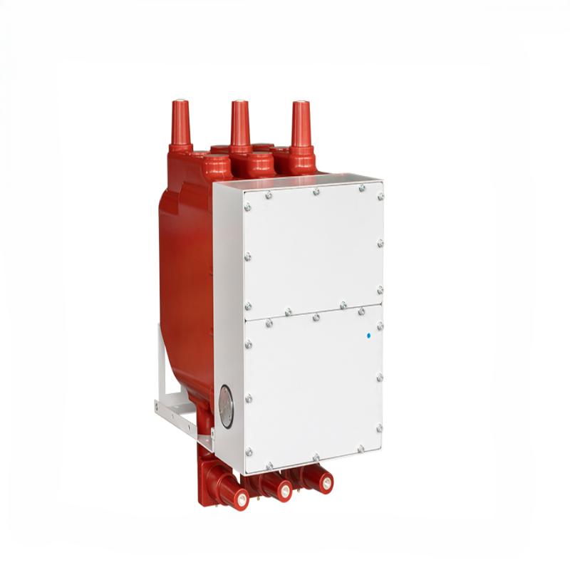
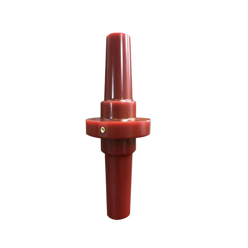
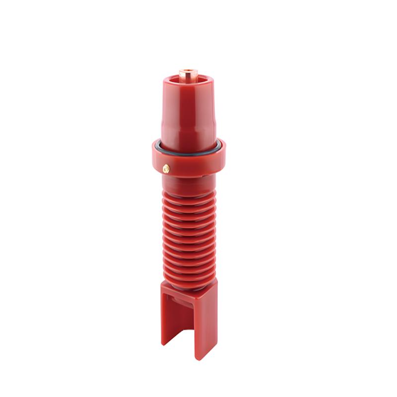
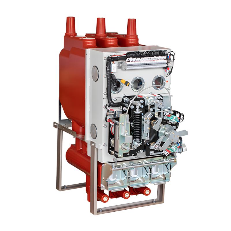
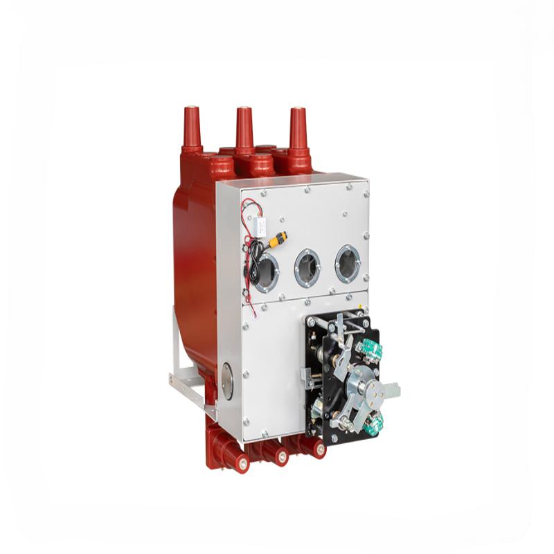
The isolation switch core PT is a specialized core component for SF6 gas free solid insulated ring main units, designed specifically for the PT circuit of 12kV/24kV medium voltage distribution systems, and responsible for precise isolation and safety control functions.
Core Features
Adopting SF6 free environmentally friendly design, combined with solid insulation structure, it meets the development needs of green power distribution and has no risk of gas leakage and pollution.
The transmission mechanism is precisely calibrated, and the opening and closing actions respond quickly and accurately, ensuring the reliability of PT circuit isolation.
Integrated multiple mechanical interlocking devices effectively prevent misoperation, comply with safety regulations in the power industry, and enhance the operational safety of the distribution system.
Compact structure, precise size suitable for solid insulated ring main unit, easy installation and maintenance, wear-resistant and corrosion-resistant, suitable for long-term stable operation.
Applicable scenarios
Suitable for 12kV/24kV SF6 free solid insulated ring main unit, widely used in medium voltage distribution systems such as distribution rooms, industrial plants, and new energy power stations. It is a key component for safe isolation and reliable operation of PT circuits.

Product dimensions

FAQ
Q: What is the core function and working principle of disconnector core?
A:

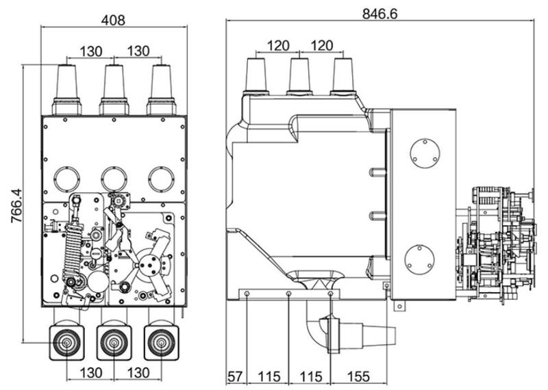
3-position disconnector core specially designed for solid insulated ring main units (RMU), mainly matching PT (potential transformer) circuits. Its core functions are: ① Realize three-position switching (closing, isolation, grounding) to ensure safe power supply and maintenance; ② Provide a visible isolation gap to isolate the power source and PT circuit, avoiding electric shock hazards during maintenance; ③ Bear normal working current and short-circuit current, ensuring stable operation of the power distribution system. Working principle: Driven by manual or electric operating mechanism, the moving contact is driven by the transmission structure to switch between three positions: In the closing position, the moving contact and static contact are closely connected to conduct current; in the isolation position, the contacts are completely separated to form a standard insulation distance; in the grounding position, the moving contact is connected to the grounding contact to ground the PT circuit, which is in line with the safety operation specifications of power systems.

Q: What advantages does the adapter busbar for solid insulated RMU have, and how to choose between copper and aluminum materials?
A:

Key advantages: ① High conductivity: Low resistance reduces power loss and avoids overheating; ② Solid insulation protection: Moisture-proof, dust-proof and corrosion-resistant, suitable for harsh indoor environments; ③ Compact structure: Fits the miniaturized design of solid insulated RMUs, saving installation space; ④ SF6-free environmental protection: Consistent with the green operation concept of solid insulated RMUs, no greenhouse gas emissions. Material selection: ① Copper: Higher conductivity (lower resistivity ~0.017Ω・mm²/m), better mechanical strength and corrosion resistance, suitable for high-load, long-term stable operation scenarios (e.g., industrial substations); ② Aluminum: Lighter weight (1/3 of copper density), lower cost, suitable for cost-sensitive, low-to-medium load scenarios (e.g., urban residential distribution networks) .

Know your supplier
Online store
On-time delivery rate
Response time
100.0%
≤4h
Company overview
Workplace: 1000m² Total staff: Highest Annual Export(usD): 300000000
Workplace: 1000m²
Total staff:
Highest Annual Export(usD): 300000000
Services
Business Type: Sales
Main Categories: Low Voltage Electrical Apparatus/Instrument meters/Production equipment/Tester/High Voltage Electrical Apparatus/Electrical fittings/Equipment Parts
Whole life care manager
Whole-life care management services for equipment procurement, use, maintenance, and after-sales, ensuring safe operation of electrical equipment, continuous control, and worry-free electricity consumption.
The equipment supplier has passed platform qualification certification and technical evaluation, ensuring compliance, professionalism, and reliability from the source.

Related Products

Related Knowledges

  • Impact of DC Bias in Transformers at Renewable Energy Stations Near UHVDC Grounding Electrodes
    Impact of DC Bias in Transformers at Renewable Energy Stations Near UHVDC Grounding ElectrodesWhen the grounding electrode of an Ultra-High-Voltage Direct Current (UHVDC) transmission system is located close to a renewable energy power station, the return current flowing through the earth can cause a rise in ground potential around the electrode area. This ground potential rise leads to a shift in the neutral-point potential of nearby power transformers, inducing DC bias (or DC offset) in their
    01/15/2026
  • HECI GCB for Generators – Fast SF6 Circuit Breaker
    1.Definition and Function1.1 Role of the Generator Circuit BreakerThe Generator Circuit Breaker (GCB) is a controllable disconnect point located between the generator and the step-up transformer, serving as an interface between the generator and the power grid. Its primary functions include isolating generator-side faults and enabling operational control during generator synchronization and grid connection. The operating principle of a GCB is not significantly different from that of a standard c
    01/06/2026
  • Distribution Equipment Transformer Testing, Inspection, and Maintenance
    1.Transformer Maintenance and Inspection Open the low-voltage (LV) circuit breaker of the transformer under maintenance, remove the control power fuse, and hang a “Do Not Close” warning sign on the switch handle. Open the high-voltage (HV) circuit breaker of the transformer under maintenance, close the grounding switch, fully discharge the transformer, lock the HV switchgear, and hang a “Do Not Close” warning sign on the switch handle. For dry-type transformer maintenance: first clean the porcel
    12/25/2025
  • How to Test Insulation Resistance of Distribution Transformers
    In practical work, insulation resistance of distribution transformers is generally measured twice: the insulation resistance between thehigh-voltage (HV) windingand thelow-voltage (LV) winding plus the transformer tank, and the insulation resistance between theLV windingand theHV winding plus the transformer tank.If both measurements yield acceptable values, it indicates that the insulation among the HV winding, LV winding, and transformer tank is qualified. If either measurement fails, pairwise
    12/25/2025
  • Design Principles for Pole-Mounted Distribution Transformers
    Design Principles for Pole-Mounted Distribution Transformers(1) Location and Layout PrinciplesPole-mounted transformer platforms should be located near the load center or close to critical loads, following the principle of “small capacity, multiple locations” to facilitate equipment replacement and maintenance. For residential power supply, three-phase transformers may be installed nearby based on current demand and future growth projections.(2) Capacity Selection for Three-Phase Pole-Mounted Tr
    12/25/2025
  • Transformer Noise Control Solutions for Different Installations
    1.Noise Mitigation for Ground-Level Independent Transformer RoomsMitigation Strategy:First, conduct a power-off inspection and maintenance of the transformer, including replacing aged insulating oil, checking and tightening all fasteners, and cleaning dust from the unit.Second, reinforce the transformer foundation or install vibration isolation devices—such as rubber pads or spring isolators—selected based on the severity of vibration.Finally, strengthen sound insulation at weak points of the ro
    12/25/2025
Haven't found the right supplier yet? Let matching verified suppliers find you. Get Quotation Now
Haven't found the right supplier yet? Let matching verified suppliers find you.
Get Quotation Now
Send inquiry
+86
Click to upload file

IEE Business will not sell or share your personal information.

Download
Get the IEE Business Application
Use the IEE-Business app to find equipment, obtain solutions, connect with experts, and participate in industry collaboration anytime, anywhere—fully supporting the development of your power projects and business.