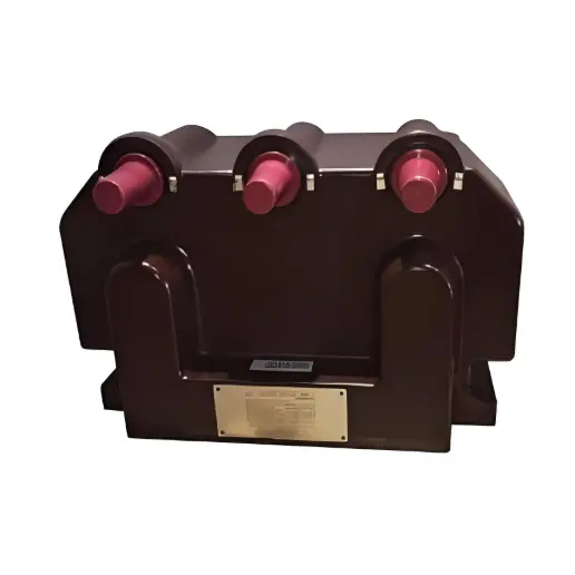
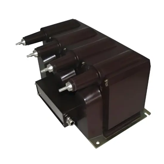
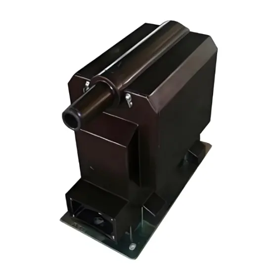
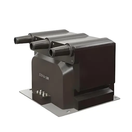
JSZV18-24RJ Voltage Transformer
Key attributes
| Brand | Wone Store |
| Model NO. | JSZV18-24RJ Voltage Transformer |
| Rated frequency | 50/60Hz |
| Primary voltage | 20kV |
| Secondary voltage | 100/220V |
| Series | JSZV |
Product descriptions from the supplier
Product Overview
JSZV18-24RJ voltage transformer, is fully enclosed casting insulation structure, the primary winding, secondary winding and the annular core all coating in the epoxy resin casting, The product adds elbow type plug part, improving the filth and moisture resistance, is widely used indoor for measuring current, electric energy and protective relaying in the isolated neutral system with the frequency 50-60Hz and highest voltage for equipment 24 kV.
Key Features
Wide Voltage Range Adaptability:The JSZV18-24RJ voltage transformer can adapt to significant voltage fluctuations based on the rated 24kV. It not only ensures normal operating voltage monitoring but also stably outputs accurate signals during transient voltage fluctuations or system voltage regulation, safeguarding the normal operation of measurement and protection systems.
Fast Response Characteristics:With high-speed voltage signal response capability, it captures voltage changes in an extremely short time and converts them into secondary-side signals. When sudden voltage surges or drops occur in the power system, it provides timely signals for relay protection devices to quickly cut off faulty circuits.
Low Hysteresis Loss:Using special magnetic materials and optimized design, it achieves extremely low hysteresis loss, reducing energy loss during conversion, improving transformer efficiency, minimizing long-term operational heating, and enhancing equipment stability and service life.
Technical Parameters
Rated primary voltage:20kV or 22kV
Rated secondary voltage:100V,100/100V,100/220V
Rated voltage of residual voltage windings:100/ 3V 、110/ 3V、 115/ 3V、 120/ 3V
Burden power factor: cosΦ=0.8(lagging)
Standards: IEC60044-2.2003 or IEC61869-1&3
Other technical parameters pls see as follow:

Remarks: Upon request we are glad to offer transformers according to other standards or with non-standard technical specs.

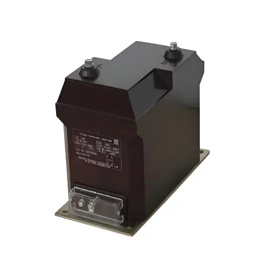
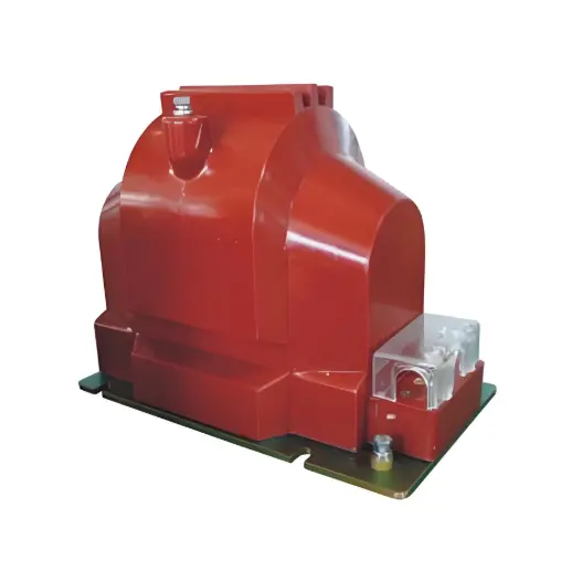
Related Products
Related Knowledges
-
 Main Transformer Accidents and Light Gas Operation Issues1. Accident Record (March 19, 2019)At 16:13 on March 19, 2019, the monitoring background reported a light gas action of No. 3 main transformer. In accordance with the Code for Operation of Power Transformers (DL/T572-2010), operation and maintenance (O&M) personnel inspected the on-site condition of No. 3 main transformer.On-site confirmation: The WBH non-electrical protection panel of No. 3 main transformer reported a Phase B light gas action of the transformer body, and the reset was ineff02/05/2026
 -
 Faults and Handling of Single-phase Grounding in 10kV Distribution LinesCharacteristics and Detection Devices for Single-Phase Ground Faults1. Characteristics of Single-Phase Ground FaultsCentral Alarm Signals:The warning bell rings, and the indicator lamp labeled “Ground Fault on [X] kV Bus Section [Y]” illuminates. In systems with a Petersen coil (arc suppression coil) grounding the neutral point, the “Petersen Coil Operated” indicator also lights up.Insulation Monitoring Voltmeter Indications:The voltage of the faulted phase decreases (in01/30/2026
 -
 Neutral point grounding operation mode for 110kV~220kV power grid transformersThe arrangement of neutral point grounding operation modes for 110kV~220kV power grid transformers shall meet the insulation withstand requirements of transformer neutral points, and shall also strive to keep the zero-sequence impedance of substations basically unchanged, while ensuring that the zero-sequence comprehensive impedance at any short-circuit point in the system does not exceed three times the positive-sequence comprehensive impedance.For 220kV and 110kV transformers in new constructi01/29/2026
 -
 Why Do Substations Use Stones, Gravel, Pebbles, and Crushed Rock?Why Do Substations Use Stones, Gravel, Pebbles, and Crushed Rock?In substations, equipment such as power and distribution transformers, transmission lines, voltage transformers, current transformers, and disconnect switches all require grounding. Beyond grounding, we will now explore in depth why gravel and crushed stone are commonly used in substations. Though they appear ordinary, these stones play a critical safety and functional role.In substation grounding design—especially when multiple gr01/29/2026
 -
 Why Must a Transformer Core Be Grounded at Only One Point? Isn't Multi-Point Grounding More Reliable?Why Does the Transformer Core Need to Be Grounded?During operation, the transformer core, along with the metal structures, parts, and components that fix the core and windings, are all situated in a strong electric field. Under the influence of this electric field, they acquire a relatively high potential with respect to ground. If the core is not grounded, a potential difference will exist between the core and the grounded clamping structures and tank, which may lead to intermittent discharge.I01/29/2026
 -
 Understanding Transformer Neutral GroundingI. What is a Neutral Point?In transformers and generators, the neutral point is a specific point in the winding where the absolute voltage between this point and each external terminal is equal. In the diagram below, pointOrepresents the neutral point.II. Why Does the Neutral Point Need Grounding?The electrical connection method between the neutral point and earth in a three-phase AC power system is called theneutral grounding method. This grounding method directly affects:The safety, reliabilit01/29/2026
Related Solutions
-
 Dedicated Vacuum Contactor Solution for Port Shore Power SystemsI. Background and ChallengesShore power systems have become core technical equipment for ports to reduce carbon emissions and noise pollution. However, these systems face two major challenges in the harsh operational environment of ports:Severe Environmental Corrosion: High humidity and salt spray in port areas cause serious corrosion to metal components and enclosures of electrical equipment, significantly impacting electrical lifespan and operational reliability.High Switching Requirements:09/13/2025
 -
 ABB Vacuum Contactor KC2 Power Supply System Technical Transformation PlanIssue OverviewThe 10kV air compressor starting system of a company utilizes the ABB vacuum contactor KC2 as the control component for the operating circuit. The dedicated wide-voltage power supply module paired with this contactor presents the following issues:Frequent failures: The power supply module fails to properly transition the voltage from 300V to 12V, resulting in fuse blowouts.Poor heat dissipation: Enclosed installation of the module leads to insufficient heat dissipation, acceler09/13/2025
 -
 Solution for Medium-Voltage Motor Control and Protection Using Vacuum Contactor-Fuse (VCF) in a Coal Conveying System1.Project BackgroundA coal conveying system comprises 15 belt conveyors driven by medium-voltage motors. The system operates under complex conditions, with motors often subjected to heavy loads and frequent starts. To address these challenges and achieve effective control and reliable protection during motor startup, the project comprehensively adopts Vacuum Contactor-Fuse (VCF) combination devices for the 6kV medium-voltage motor power distribution. This solution details the technical features,09/13/2025


