

| Brand | MV Switchgear Accessories |
| Model NO. | Isolator Switch DNH8(HGL) Series Load-Disconnector Switch |
| Rated normal current | 3150A |
| number of poles | 4p |
| Series | DNH8(HGL) |
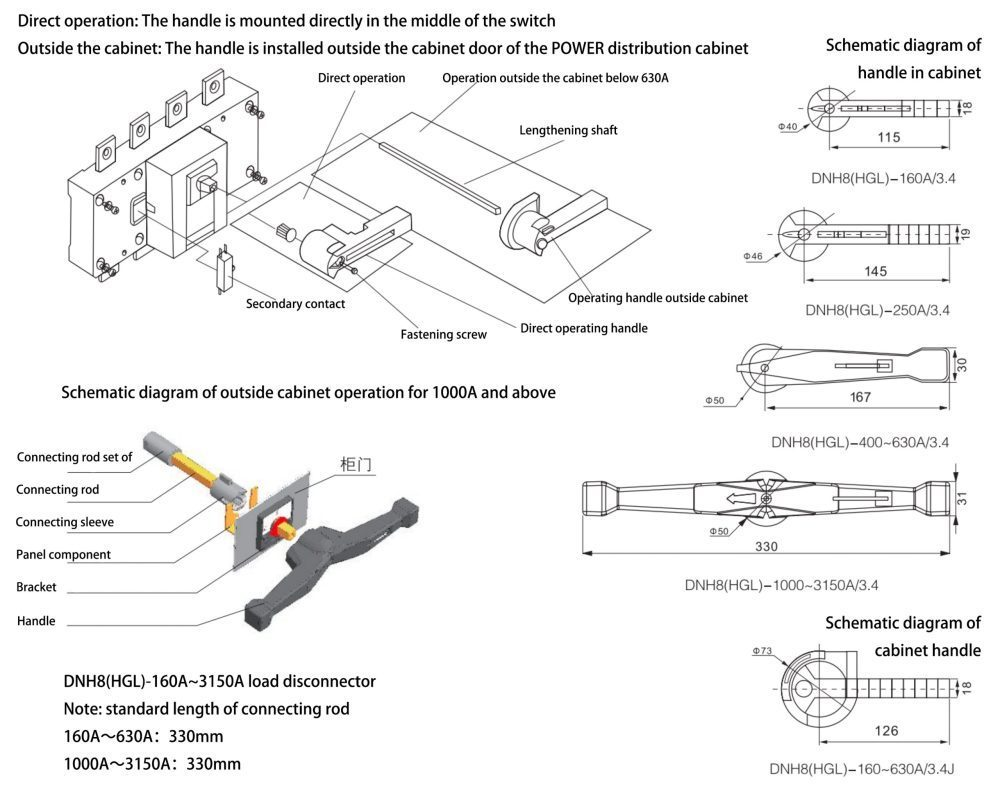
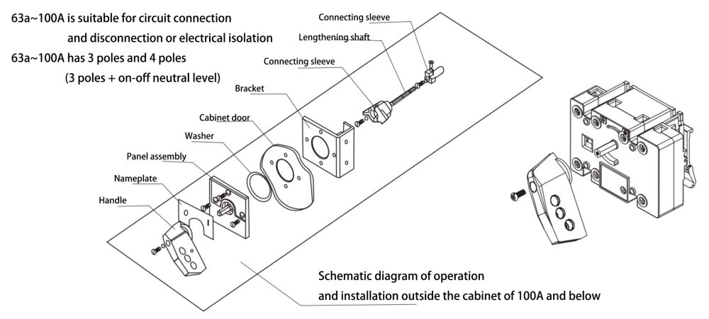
Pole Isolator Switches DNH8(HGL) series are designed for use in a variety of applications where circuit turn-on and turn-off or electrical isolation is required. They are available in seven different models, ranging from 63A to 3150A, and feature a modular design with three and four levels (three levels + neutral level for turn-on and turn-off).
Electrical isolation switch is also equipped with a front-side window that indicates the contact’s on/off state, and a rear observation window that allows for direct observation of the contact’s on-off state.
Compatible with various low-voltage distribution cabinets, it can meet the distribution isolation needs of multiple scenarios such as industry and construction. The specific compatible cabinets and details are as follows: GGD fixed low-voltage switchgear, GCK withdrawable low-voltage switchgear, GCS withdrawable low-voltage switchgear, XL-21 power cabinet, etc
Temperature Range: The ambient air temperature should remain between -5 °C and +40 °C, with relative humidity not exceeding 95%.
Altitude: Installation altitude must not exceed 2000 meters.
Environment: The switch should be used in environments free from explosive hazards and where rain or snow does not intrude.
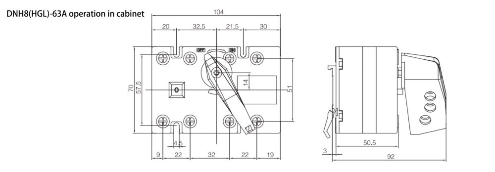
| Rated current In (A) | 63A |
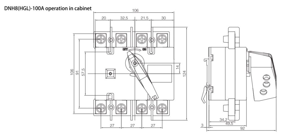
100A | 160A | 250A | 630A |
||||||||
| Contract heating current Ith (A) | 40 |
63 | 80 | 100 | 125 | 160 | 200 | 250 | 315 | 400 | 500 | 630 | |
| Rated insulation voltage Ui (V) (Installation class IV) | 690 |
690 | 1000 | 1000 | 1000 |
||||||||
| Dielectric strength (V) | 1890 |
1890 | 2200 | 2200 | 2200 |
||||||||
| Rated impulse withstand voltage Uimp kV | 8 |
8 | 12 | 12 | 12 |
||||||||
| Rated operating current le (A) | AC-21B |
40 |
63 | 80 | 100 | 125 | 160 | 200 | 250 | 315 | 400 | 500 | 630 |
AC-22B |
40 |
63 | 80 | 100 | 125 | 160 | 200 | 250 | 315 | 400 | 500 | 630 |
|
AC-23B |
40 |
63 | 80 | 100 | 125 | 160 | 200 | 250 | 315 | 400 | 500 | 630 | |
| Motor power P (kW) | 400V |
18.5 | 25 | 40 | 40 | 63 | 80 | 100 | 132 | 160 | 220 | 280 | 315 |
| Rated short-time endurance current lcw (kA Rms) 1s | 2 |
2 | 2 | 2 | 6 | 6 | 9 | 9 | 12.6 | 12.6 | 12.6 | 12.6 |
|
| Rated breaking capacity Icn (A Rms) AC-23B 400V | 320 |
504 | 640 | 800 | 1000 | 1080 | 1600 | 2000 | 2520 | 3200 | 4000 | 5040 | |
| Rated switching capacity Icm (A Rms) AC-23B 400V | 400 |
630 | 800 | 1000 | 1250 | 1600 | 2000 | 2500 | 3150 | 4000 | 5000 | 6300 | |
| Rated short-circuit switching capacity Icm (kA peak) | 2.84 |
2.84 | 2.84 | 2.84 | 9.2 | 9.2 | 15.3 | 15.3 | 25.2 | 25.2 | 25.2 | 25.2 |
|
| Mechanical life 400V | 1700 |
1700 | 1700 | 1700 | 1400 | 1400 | 1400 | 1400 | 800 | 800 | 800 | 800 |
|
| Electrical life 400V | 300 |
300 | 300 | 300 | 200 | 200 | 200 | 200 | 200 | 200 | 200 | 200 | |
| Operating torque (Nm) | 1.2 |
1.2 | 1.2 | 1.2 | 6.5 | 6.5 | 10 | 10 | 21 | 21 | 21 | 21 |
|
| Weight (kg) | 3P |
0.4 | 0.4 | 0.55 | 0.55 | 1.2 | 1.2 | 2 | 2 | 4.4 | 4.4 | 4.9 | 4.9 |
4P |
0.42 | 0.42 | 0.62 | 0.62 | 1.4 | 1.4 | 2.35 | 2.35 | 5.5 | 5.5 | 6.3 | 6.3 | |
| Rated current In (A) | 1600A |
3150A |
||||||
| Contract heating current Ith (A) | 1000 |
1250 | 1600 | 2000 | 2500 | 3150 |
||
| Rated insulation voltage Ui (V) (Installation class IV) | 1000 |
1000 |
||||||
| Dielectric strength (V) | 2200 |
2200 |
||||||
| Rated impulse withstand voltage Uimp kV | 12 |
12 |
||||||
| Rated operating current le (A) | AC-21B |
1000 |
1250 | 1600 | 2000 | 2500 | 3150 | |
AC-22B |
/ | / | / | / | / | / |
||
AC-23B |
/ | / | / | / | / | / |
||
| Motor power P (kW) | 400V |
560 | 560 | 560 | 710 | 710 | 710 |
|
| Rated short-time endurance current lcw (kA Rms) 1s | 30 |
30 | 30 | 50 | 50 | 50 |
||
| Rated breaking capacity Icn (A Rms) AC-23B 400V | 1500 |
1875 | 2400 | 3000 | 3750 | 4725 |
||
| Rated switching capacity Icm (A Rms) AC-23B 400V | 1500 |
1875 | 2400 | 3000 | 3750 | 4725 |
||
| Rated short-circuit switching capacity Icm (kA peak) | 63 |
63 | 63 | 105 | 105 | 105 |
||
| Mechanical life 400V | 500 |
500 | 500 | 500 | 500 | 500 |
||
| Electrical life 400V | 100 |
100 | 100 | 100 | 100 | 100 |
||
| Operating torque (Nm) | 37 |
37 | 37 | 50 | 50 | 50 |
||
| Weight (kg) | 3P |
13.2 | 14.6 | 15.6 | 25.5 | 25.5 | 31 |
|
4P |
14.8 | 17.1 | 18 | 37.5 | 37.5 | 51.5 |
||
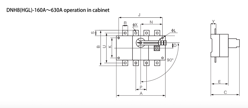
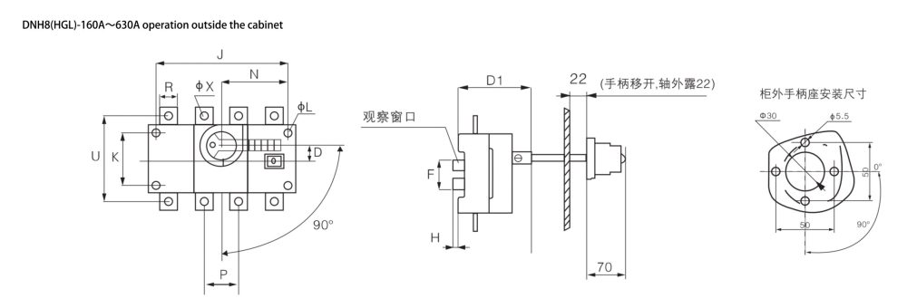
Specifications |
Overall dimension | Installation dimension |
|||||||||||||||||
In |
A | B | C | D | D1 | E | φL | F | H | N | P | R | S | U | φX | Y | J | K |
|
125A/3 |
140 | 135 | 121 | 15 | 93 | 71 | 5.5 | 50 | 10 | 75 | 36 | 20 | 25 | 115 | 9 | 24 | 120 | 65 |
|
125A/4 |
170 | 135 | 121 | 15 | 93 | 71 | 5.5 | 50 | 10 | 75 | 36 | 20 | 25 | 115 | 9 | 24 | 150 | 65 |
|
160A/3 |
140 | 135 | 121 | 15 | 93 | 71 | 5.5 | 50 | 10 | 75 | 36 | 20 | 25 | 115 | 9 | 24 | 120 | 65 | |
160A/4 |
170 | 135 | 121 | 15 | 93 | 71 | 5.5 | 50 | 10 | 75 | 36 | 20 | 25 | 115 | 9 | 24 | 150 | 65 |
|
200A/3 |
180 | 170 | 144 | 20 | 104 | 84 | 5.5 | 79 | 15 | 105 | 50 | 25 | 30 | 140 | 11 | 25 | 160 | 90 |
|
200A/4 |
230 | 170 | 144 | 20 | 104 | 84 | 5.5 | 79 | 15 | 105 | 50 | 25 | 30 | 140 | 11 | 25 | 210 | 90 |
|
250A/3 |
180 | 170 | 144 | 20 | 104 | 84 | 5.5 | 79 | 15 | 105 | 50 | 25 | 30 | 140 | 11 | 25 | 160 | 90 |
|
250A/4 |
230 | 170 | 144 | 20 | 104 | 84 | 5.5 | 79 | 15 | 105 | 50 | 25 | 30 | 140 | 11 | 25 | 210 | 90 |
|
315A/3 |
230 | 240 | 188 | 30 | 137 | 115 | 7 | 95 | 20 | 135 | 65 | 32 | 40 | 206 | 11 | 37 | 210 | 140 |
|
315A/4 |
290 | 240 | 188 | 30 | 137 | 115 | 7 | 95 | 20 | 135 | 65 | 32 | 40 | 206 | 11 | 37 | 270 | 140 |
|
400A/3 |
230 | 240 | 188 | 30 | 137 | 115 | 7 | 95 | 20 | 135 | 65 | 32 | 40 | 206 | 11 | 37 | 210 | 140 |
|
400A/4 |
290 | 240 | 188 | 30 | 137 | 115 | 7 | 95 | 20 | 135 | 65 | 32 | 40 | 206 | 11 | 37 | 270 | 140 |
|
500A/3 |
230 | 260 | 188 | 30 | 137 | 115 | 7 | 95 | 20 | 135 | 65 | 40 | 50 | 220 | 13 | 37.5 | 210 | 140 |
|
500A/4 |
290 | 260 | 188 | 30 | 137 | 115 | 7 | 95 | 20 | 135 | 65 | 40 | 50 | 220 | 13 | 37.5 | 270 | 140 |
|
630A/3 |
230 | 260 | 188 | 30 | 137 | 115 | 7 | 95 | 20 | 135 | 65 | 40 | 50 | 220 | 13 | 37.5 | 210 | 140 |
|
630A/4 |
290 | 260 | 188 | 30 | 137 | 115 | 7 | 95 | 20 | 135 | 65 | 40 | 50 | 220 | 13 | 37.5 | 270 | 140 |
|
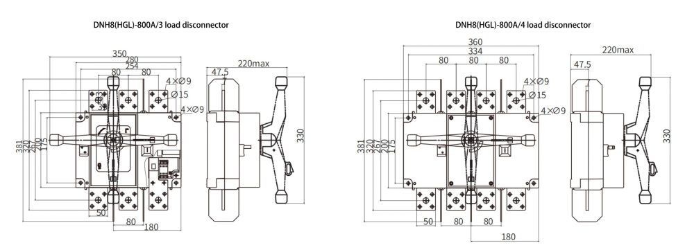
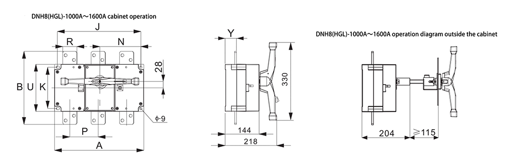
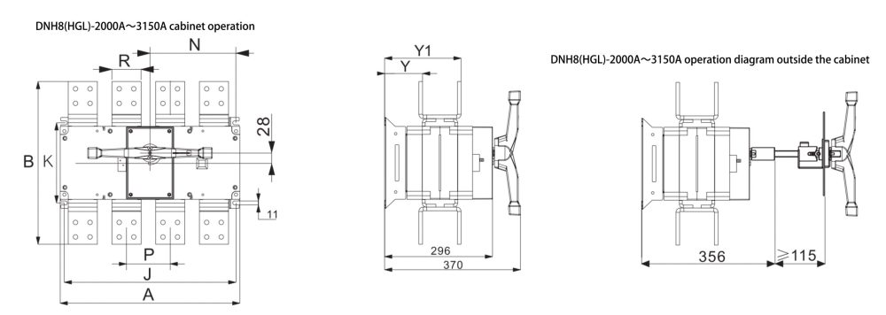
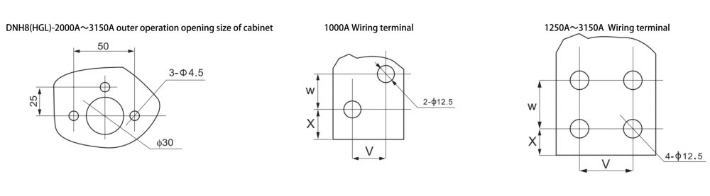
Specifications |
Overall dimension | Installation dimension |
|||||||||||
| In | A |
B | C | D | D1 | E | φL | F | H | N | P | J | K |
| 1000A/3 | 378 |
308 | 174 | 120 | 60 | 200 | 35 | 20 | 16.5 | 49 | 353 | 175 |
|
| 1000A/4 | 493 |
310 | 235 | 120 | 60 | 200 | 35 | 20 | 16.5 | 48 | 471 | 174 |
|
| 1250A/3 | 378 |
336 | 174 | 120 | 80 | 200 | 40 | 35 | 16 | 49 | 353 | 175 |
|
| 1250A/4 | 493 |
338 | 235 | 120 | 80 | 200 | 40 | 35 | 16 | 48 | 471 | 174 |
|
| 1600A/3 | 378 |
336 | 174 | 120 | 80 | 200 | 40 | 35 | 16 | 50 | 353 | 175 |
|
| 1600A/4 | 493 |
338 | 235 | 120 | 80 | 200 | 40 | 35 | 16 | 49 | 471 | 174 |
|
| 2000A/3 | 378 |
445 | 174 | 120 | 80 | 200 | 40 | 40 | 20 | 103 | 50 | 353 | 220 |
| 2000A/4 | 493 |
447 | 235 | 120 | 80 | 200 | 40 | 40 | 20 | 104 | 50 | 471 | 220 |
| 2500A/3 | 378 |
445 | 174 | 120 | 80 | 200 | 40 | 40 | 20 | 103 | 65 | 353 | 220 |
| 2500A/4 | 493 |
447 | 235 | 120 | 80 | 200 | 40 | 40 | 20 | 104 | 65 | 471 | 220 |
| 3150A/3 | 378 |
492 | 174 | 120 | 120 | 200 | 50 | 50 | 21 | 77 | 65 | 353 | 220 |
| 3150A/4 | 493 |
494 | 235 | 120 | 120 | 200 | 50 | 50 | 21 | 78 | 65 | 471 | 220 |
The DNH8(HGL) series 3 phase isolator switch provides essential functionality for electrical isolation and circuit control in various applications. Available in models ranging from 63A to 3150A, this modular design incorporates three and four levels (including a neutral level for circuit operation). Additionally, it features a front-side window for indicating the contact state and a rear observation window for easy monitoring.


