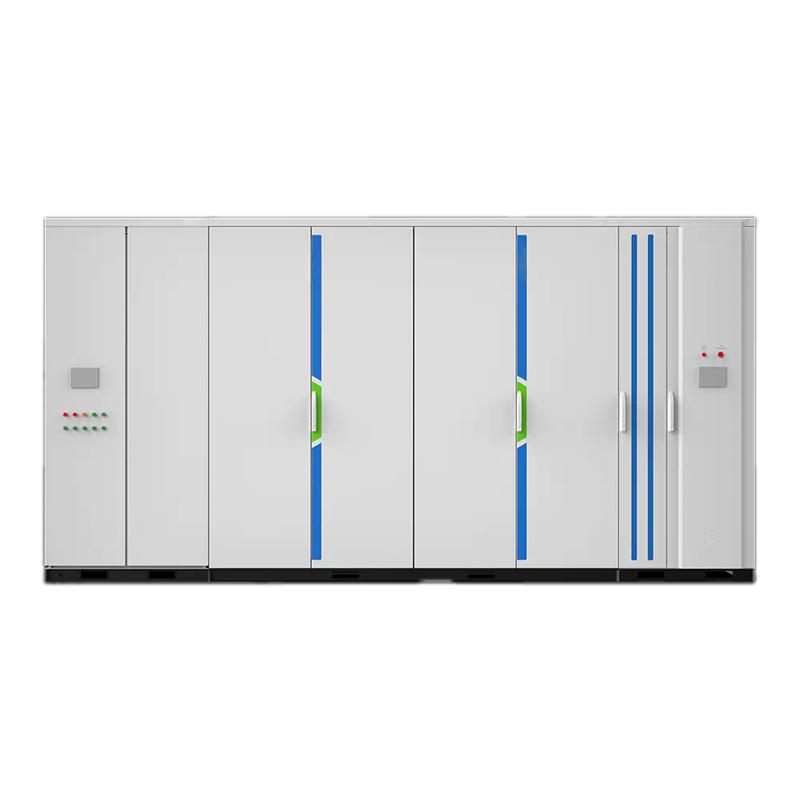
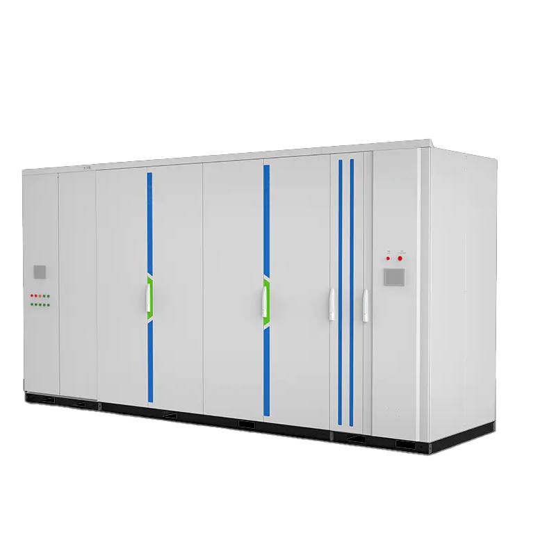
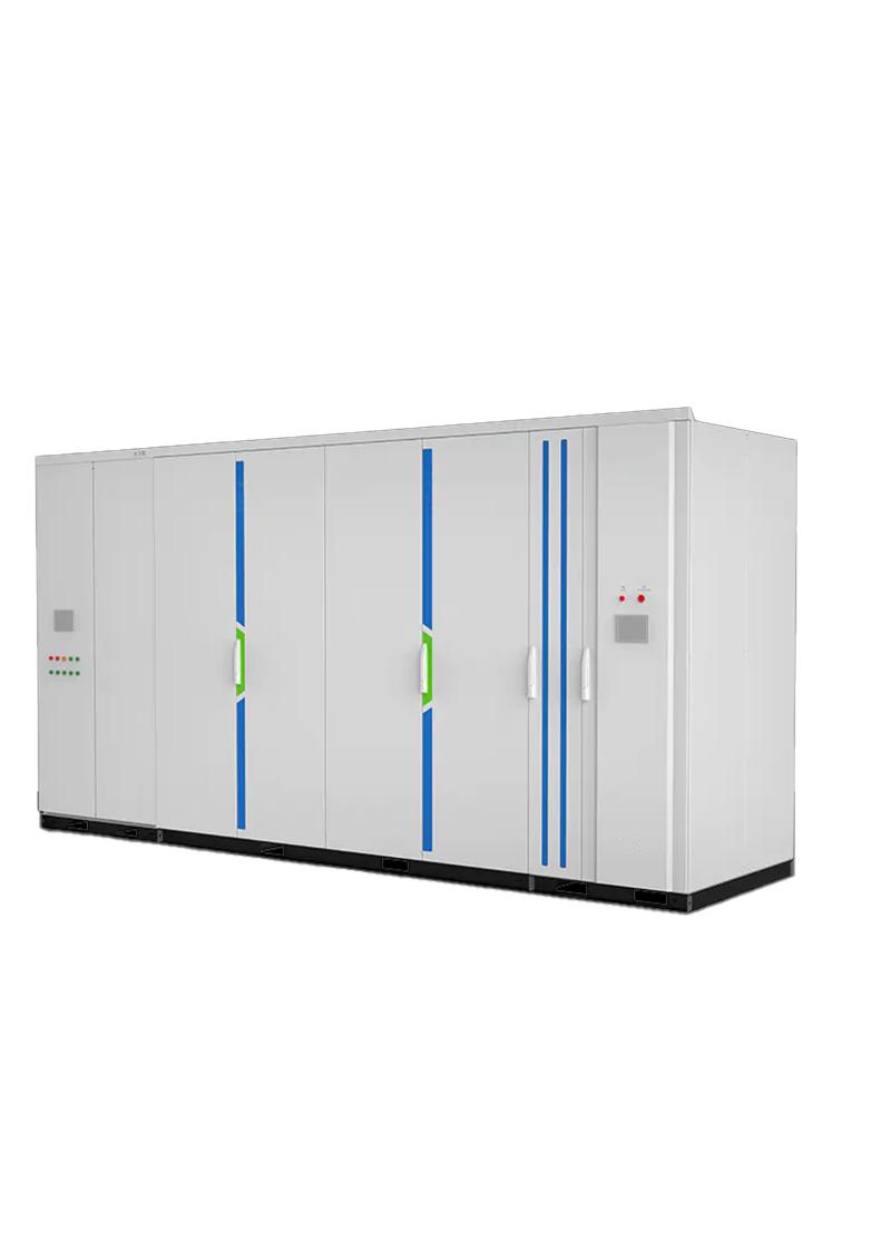
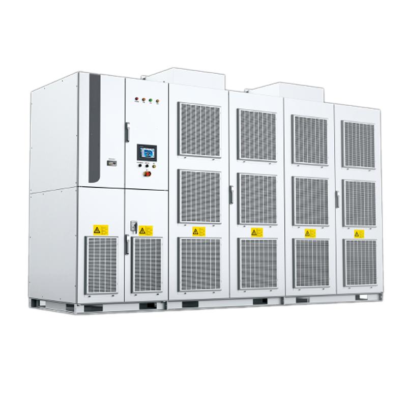
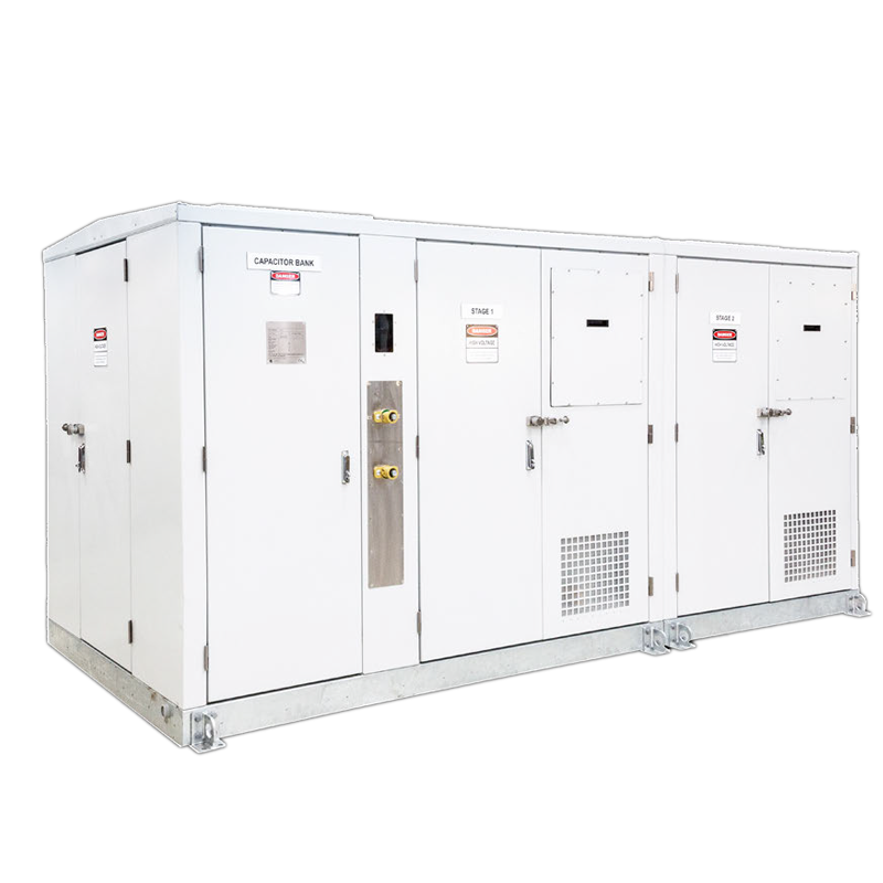
6kV Outdoor static var generator(SVG)
Key attributes
| Brand | RW Energy |
| Model NO. | 6kV Outdoor static var generator(SVG) |
| Rated voltage | 6kV |
| Cooling mode | Forced air cooling |
| Range of rated capacity | 1~4 Mvar |
| Series | RSVG |
Product descriptions from the supplier
Product Overview
The 6kV outdoor static reactive power generator (SVG) is a high-performance dynamic reactive power compensation device designed specifically for medium and high voltage distribution networks. It adopts an outdoor specific design (protection level IP44) and is suitable for complex outdoor working conditions. The product uses a multi chip DSP+FPGA as the control core, integrating instantaneous reactive power theory control technology, FFT fast harmonic calculation technology, and high-power IGBT driving technology. It is directly connected to the power grid through a cascaded power unit structure, without the need for additional boosting transformers, and can quickly and continuously provide capacitive or inductive reactive power. At the same time, it achieves dynamic harmonic compensation, effectively improves power quality, enhances grid stability, and has high reliability, ease of operation, and excellent performance. It is the core compensation solution for outdoor industrial scenes and power systems.
System structure and working principle
Core structure
Cascade power unit: adopting a cascade design, integrating multiple sets of high-performance IGBT modules, and withstanding high voltage of 6kV~35kV through series connection to ensure stable operation of the equipment.
Control core: Equipped with a multi chip DSP+FPGA control system, it has fast computing speed and high control accuracy. It communicates with various power units through Ethernet, RS485 and other interfaces to achieve status monitoring and command issuance.
Auxiliary structure: Configure a grid side coupling transformer with functions of filtering, current limiting, and suppressing current change rate; The outdoor cabinet meets the IP44 protection standard and is suitable for harsh outdoor environments.
Working principle
The controller monitors the load current of the power grid in real-time. Based on the theory of instantaneous reactive power and FFT fast harmonic calculation technology, it instantly analyzes the required reactive current and harmonic components. Through PWM pulse width modulation technology, it controls the switching state of the IGBT module, generates reactive compensation current synchronized with the grid voltage and offset by 90 degrees in phase, accurately offsets the reactive power of the load, and dynamically compensates for harmonic components. The ultimate goal is to only transmit active power on the grid side, achieving multiple objectives of power factor optimization, voltage stability, and harmonic suppression, ensuring efficient and stable operation of the power system.
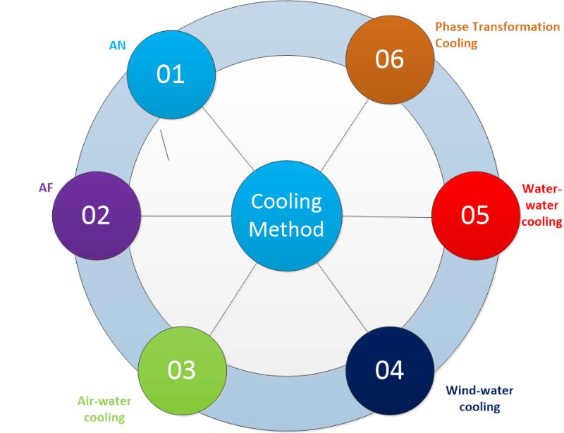
Cooling method
Forced cooling (AF/Air Cooling)
Water Cooling
Heat dissipation mode:
Main Features
Advanced technology and comprehensive compensation: Integrating DSP+FPGA dual core control, instantaneous reactive power theory, and FFT harmonic calculation technology, it can not only automatically and continuously smooth adjust capacitive/inductive reactive power, but also dynamically compensate for harmonics, achieving integrated management of "reactive power & harmonics".
Dynamic precision and rapid response: response time<5ms, compensation current resolution 0.5A, supports stepless smooth compensation, effectively suppresses voltage flicker caused by impact loads (such as electric arc furnaces and frequency converters), and ensures stable operation of equipment.
Stable and reliable, suitable for outdoor use: adopting a dual power supply design, supporting seamless backup switching; Redundant design meets the operational requirements of N-2, with multiple protection functions (overvoltage, undervoltage, overcurrent, overheating, etc.) fully covering fault scenarios; IP44 outdoor protection level, able to withstand operating temperatures of -35 ℃~+40 ℃, humidity ≤ 90%, and seismic intensity of VIII degrees, suitable for complex outdoor environments.
Efficient and environmentally friendly, with lower energy consumption: system power loss<0.8%, harmonic distortion rate THDi<3%, minimal pollution to the power grid; No additional transformer losses, balancing energy conservation and environmental protection needs.
Flexible adaptation and strong scalability: supports multiple operating modes such as constant reactive power, constant power factor, and constant voltage; Compatible with multiple communication protocols such as Modbus RTU and IEC61850; It can achieve multi machine parallel networking, multi bus comprehensive compensation, and modular design for easy expansion.
Easy to operate, maintenance tips: The device design takes into account usability, and attention should be paid to timely cleaning of the filter cotton. It is recommended to clean it at least once every two weeks to ensure heat dissipation and operational stability.
Technical Specifications
Name |
Specification |
Rated voltage |
6kV±10%~35kV±10% |
Assessment point voltage |
6kV±10%~35kV±10% |
Input voltage |
0.9~ 1.1pu; LVRT 0pu(150ms), 0.2pu(625ms) |
Frequency |
50/60Hz; Allow short-term fluctuations |
Output capacity |
±0.1Mvar~±200 Mvar |
Starting power |
±0.005Mvar |
Compensation current resolution |
0.5A |
Response time |
<5ms |
Overload capacity |
>120% 1min |
Power loss |
<0.8% |
THDi |
<3% |
Power supply |
Dual power supply |
Control power |
380VAC, 220VAC/220VDC |
Reactive power regulation mode |
Capacitive and inductive automatic continuous smooth adjustment |
Communication interface |
Ethernet, RS485, CAN, Optical fiber |
Communication protocol |
Modbus_RTU, Profibus, CDT91, IEC61850- 103/104 |
Running mode |
Constant device reactive power mode, constant assessment point reactive power mode, constant assessment point power factor mode, constant assessment point voltage mode and load compensation mode |
Parallel mode |
Multi machine parallel networking operation, multi bus comprehensive compensation and multi group FC comprehensive compensation control |
Protection |
Cell DC overvoltage, Cell DC undervoltage, SVG overcurrent, drive fault, power unit overvoltage, overcurrent, overtemperature and communication fault; Protection input interface, protection output interface, abnormal system power supply and other protection functions. |
Fault handling |
Adopt redundant design to meet N-2 operation |
Cooling mode |
Water cooling/Air cooling |
IP degree |
IP30(indoor); IP44(outdoor) |
Storage temperature |
-40℃~+70℃ |
Running temperature |
-35℃~ +40℃ |
Humidity |
<90% (25℃), no condensation |
Altitude |
<=2000m (above 2000m customized) |
Earthquake intensity |
Ⅷ degree |
Pollution level |
Grade IV |
Specifications and dimensions of 6kV outdoor products
Air cooling type:
Voltage class(kV) |
Rated capacity(Mvar) |
Dimension |
Weight(kg) |
Reactor type |
6 |
1.0~6.0 |
5200*2438*2560 |
6500 |
Iron core reactor |
7.0~12.0 |
6700*2438*2560 |
6450~7000 |
Air core reactor |
Water cooling type
Voltage class(kV) |
Rated capacity(Mvar) |
Dimension |
Weight(kg) |
Reactor type |
6 |
1.0~15.0 |
5800*2438*2591 |
7900~8900 |
Air core reactor |
Note:
1. Capacity (Mvar) refers to the rated regulation capacity within the dynamic regulation range from inductive reactive power to capacitive reactive power.
2. The air core reactor is used for the equipment, and there is no cabinet, so the placement space needs to be planned separately.
3. The above dimensions are for reference only. The company reserves the right to upgrade and improve the products. The product dimensions are subject to change without notice.
Application scenarios
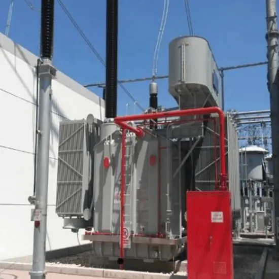
Power system: Adapt to various levels of distribution networks, stabilize grid voltage, balance three-phase systems, reduce power losses, and enhance power transmission capacity.
In the field of heavy industry: metallurgy (electric arc furnace, induction furnace), mining (hoist), ports (crane) and other scenarios, compensating for reactive power and harmonics of impact loads, and suppressing voltage flicker.
Petrochemical and manufacturing industry: Provide compensation for asynchronous motors, transformers, thyristor converters, frequency converters and other equipment, improve power quality, and ensure production continuity.
In the field of new energy, wind farms, photovoltaic power stations, etc. are used to alleviate power fluctuations caused by intermittent power generation and ensure stable grid connected voltage.
Transportation and urban construction: electrified railways (traction power supply system), urban rail transit (elevators, cranes), solving negative sequence and reactive power problems; Urban distribution network renovation to enhance power supply reliability.
Other scenarios: outdoor working conditions that require reactive power compensation and harmonic control, such as lighting equipment, welding machines, resistance furnaces, quartz melting furnaces, etc.
SVG capacity selection core: steady-state calculation & dynamic correction. Basic formula: Q ₙ=P × [√ (1/cos ² π₁ -1) - √ (1/cos ² π₂ -1)] (P is active power, power factor before compensation, target value of π₂, often requires ≥ 0.95). Load correction: impact/new energy load x 1.2-1.5, steady-state load x 1.0-1.1; High altitude/high temperature environment x 1.1-1.2. New energy projects must comply with standards such as IEC 61921 and ANSI 1547, with an additional 20% low-voltage ride through capacity reserved. It is recommended to leave 10% -20% expansion space for modular models to avoid compensation failure or compliance risks caused by insufficient capacity.
What are the differences between SVG, SVC, and capacitor cabinets?
The three are the mainstream solutions for reactive power compensation, with significant differences in technology and applicable scenarios:
Capacitor cabinet (passive): The lowest cost, graded switching (response 200-500ms), suitable for steady-state loads, requires additional filtering to prevent harmonics, suitable for budget limited small and medium-sized customers and entry-level scenarios in emerging markets, in compliance with IEC 60871.
SVC (Semi Controlled Hybrid): Medium cost, continuous regulation (response 20-40ms), suitable for moderate fluctuating loads, with a small amount of harmonics, suitable for traditional industrial transformation, in compliance with IEC 61921.
SVG (Fully Controlled Active): High cost but excellent performance, fast response (≤ 5ms), high-precision stepless compensation, strong low-voltage ride through capability, suitable for impact/new energy loads, low harmonic, compact design, in line with CE/UL/KEMA, is the preferred choice for high-end markets and new energy projects.
Selection core: Choose capacitor cabinet for steady-state load, SVC for moderate fluctuation, SVG for dynamic/high-end demand, all of which need to match international standards such as IEC.

Related Products
-
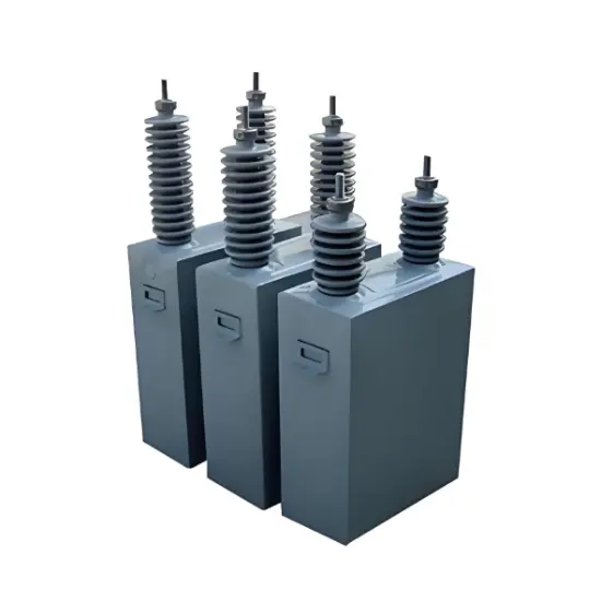
7.75kV 475kVar High Voltage Power Factor Capacitor Bank
-
15kV High Voltage Shunt Capacitor 400kvar Reduce Power Loss
-
6KV High Voltage Power Capacitor Single Phase With SS Case
-
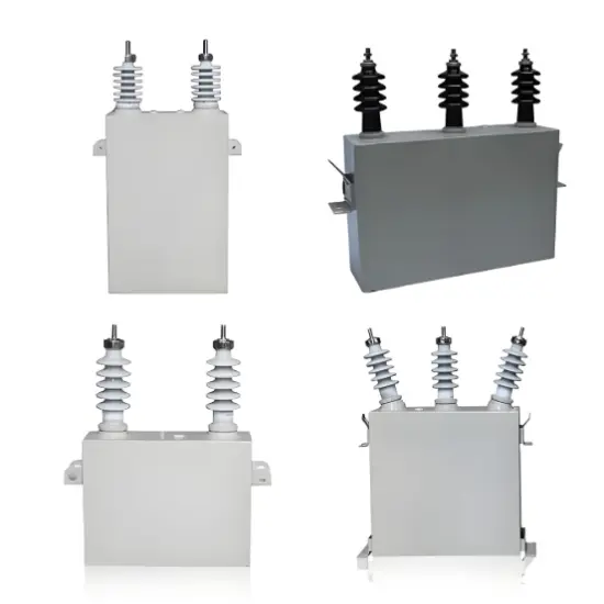
0.4kV/6kV/10kV Filter capacitor (FC)
-
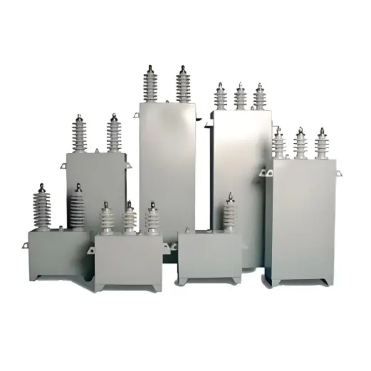
Medium Voltage Shunt Capacitors

-
PQactiF Series Active filter

-
ACUS-E Series Metal Enclosed Capacitor Banks
Related Knowledges
-
 How to Judge, Detect and Troubleshoot Transformer Core Faults1. Hazards, Causes, and Types of Multi-Point Grounding Faults in Transformer Cores1.1 Hazards of Multi-Point Grounding Faults in the CoreUnder normal operation, a transformer core must be grounded at only one point. During operation, alternating magnetic fields surround the windings. Due to electromagnetic induction, parasitic capacitances exist between the high-voltage and low-voltage windings, between the low-voltage winding and the core, and between the core and the tank. The energized windin01/27/2026
 -
 A Brief Discussion on the Selection of Grounding Transformers in Boost StationsA Brief Discussion on the Selection of Grounding Transformers in Boost StationsThe grounding transformer, commonly referred to as "grounding transformer," operates under the condition of being no-load during normal grid operation and overloaded during short-circuit faults. According to the difference in filling medium, common types can be divided into oil-immersed and dry-type; according to phase number, they can be classified into three-phase and single-phase grounding transformers. The groundi01/27/2026
 -
 Impact of DC Bias in Transformers at Renewable Energy Stations Near UHVDC Grounding ElectrodesImpact of DC Bias in Transformers at Renewable Energy Stations Near UHVDC Grounding ElectrodesWhen the grounding electrode of an Ultra-High-Voltage Direct Current (UHVDC) transmission system is located close to a renewable energy power station, the return current flowing through the earth can cause a rise in ground potential around the electrode area. This ground potential rise leads to a shift in the neutral-point potential of nearby power transformers, inducing DC bias (or DC offset) in their01/15/2026
 -
 HECI GCB for Generators – Fast SF6 Circuit Breaker1.Definition and Function1.1 Role of the Generator Circuit BreakerThe Generator Circuit Breaker (GCB) is a controllable disconnect point located between the generator and the step-up transformer, serving as an interface between the generator and the power grid. Its primary functions include isolating generator-side faults and enabling operational control during generator synchronization and grid connection. The operating principle of a GCB is not significantly different from that of a standard c01/06/2026
 -
 Distribution Equipment Transformer Testing, Inspection, and Maintenance1.Transformer Maintenance and Inspection Open the low-voltage (LV) circuit breaker of the transformer under maintenance, remove the control power fuse, and hang a “Do Not Close” warning sign on the switch handle. Open the high-voltage (HV) circuit breaker of the transformer under maintenance, close the grounding switch, fully discharge the transformer, lock the HV switchgear, and hang a “Do Not Close” warning sign on the switch handle. For dry-type transformer maintenance: first clean the porcel12/25/2025
 -
 How to Test Insulation Resistance of Distribution TransformersIn practical work, insulation resistance of distribution transformers is generally measured twice: the insulation resistance between thehigh-voltage (HV) windingand thelow-voltage (LV) winding plus the transformer tank, and the insulation resistance between theLV windingand theHV winding plus the transformer tank.If both measurements yield acceptable values, it indicates that the insulation among the HV winding, LV winding, and transformer tank is qualified. If either measurement fails, pairwise12/25/2025
Related Solutions
-
 Distribution automation systems solutionsWhat are the difficulties in overhead line operation and maintenance?Difficulty one:Overhead lines of distribution network have wide coverage,complicatedterrain,many radiation branches and distributed power supply,resultingin "many line faults and difficulty in fault troubleshooting".Difficulty Two:Manual troubleshooting is time-consuming and laborious.Meanwhile,therunning current,voltage and switching state of the line cannot be graspedin real time,because of the lack of intelligent technical m04/22/2025
 -
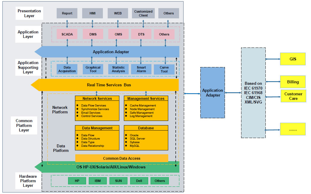 RW8000 DMS Distribution Management System SolutionsOverviewNowadays, the development trend of power grid is intellectualization. As an important part of power grid, the power distribution system is very close to the customers and it has to run properly. The distribution management system (DMS)played an important role in it.Introduction:RW8000 power distribution management system (DMS) is designed for the smart grids. It is based on real-time application, centered on distribution network operation and management, focusing on the business process09/07/2023
 -
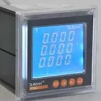 High-Precision Electrical Parameter Monitoring System Solution1.IntroductionWith the increasingly stringent requirements for power supply quality in high-end facilities such as precision manufacturing, medical diagnosis, and data centers, traditional power monitoring systems, due to their low sampling accuracy and weak data analysis capabilities, can no longer meet the demand for deep insight and precise management of power quality. In response, we are introducing a new generation High-Precision Electrical Parameter Monitoring System. With millisecond-l09/28/2025


