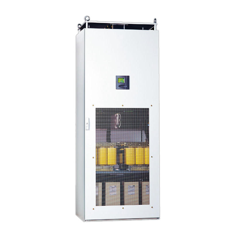
| Brand | ROCKWILL |
| Model NO. | Dynacomp Thyristor-Switched Capacitor Bank |
| Rated voltage | 400V |
| Rated capacity | 400kVA |
| Series | Dynacomp |
The Dynacomp is a circuit consisting of capacitors and reactors switched on the network by solid state power electronics, without any moving part. A three-phase Dynacomp circuit is represented below. Single-phase
Dynacomps are also available. The Dynacomp can compensate low voltage equipment for nominal voltages from 380V up to 690V.
The thyristors are fired at the natural zero crossing of the capacitive current. As a result, capacitors are connected to the network without transients.
The control is such that only complete cycles of the current are allowed. This ensures that no harmonics or transients are generated by the Dynacomp.
This connection is valid for closed-loop and/or external trigger control systems. For other configurations, please consult us. Measurements provided by the controller are network measurements in any case
Single-phase systems are also available. Please consult us
External trigger system, if needed, is made through one or two inputs (opto1 and opto2: 15-24Vdc)
Switching of charged capacitors result in large transients when the capacitor and network voltages are in phase opposition at the closing instant. This is why conventional banks always have delays (~1 minute) between switching on/off the capacitors. This delay permits the discharge of the capacitors through discharge resistors, but limits the utilisation of conventional capacitor banks for rapidly fluctuating loads requiring frequent switchings.
As the switching of the Dynacomp does not require the discharge of the capacitors, the utilisation of the Dynacomp for the compensation of any load with rapid variations is possible. During its cycle, a crane requires variable amounts of reactive power. The whole crane cycle lasts about one minute. Compensation with conventional banks is not possible for this operation: the cycle is too short and the required reactive power is too large. The Dynacomp improves the power factor by reducing the reactive current drawn from the grid. This also results in reduced current drawn from the supply system. The presence of 7% detuning reactor helps in harmonic absorption which is reflected in reduced THDV levels.
Welding equipment typically draws high welding current for a very short time. As a result, the repetitive impermissible voltage variations may result.
In the figures below, 4 steps of 150 kvar are switched on for the compensation of a 210 kVA single phase welder with the use of an external signal for instantaneous response time (voltage drop compensation). These figures show clearly that the voltage drop due to the welding machine is totally reduced. Perturbation to sensitive devices like PLC, computers, lighting, ... are avoided.
In addition to this positive effect, the quality of the welding is considerably improved leading to a better quality of the final product. At the same time the power consumption of the production line is significantly lowered.
Rolling mill normally employs large DC drives where the metal is rolled from billets to various sheet thicknesses. The load on the network depends on the type of “Pass” and grade of material being rolled. A typical load cycle lasts from a few minutes to several minutes during which the reactive power demand varies rapidly.
A classical solution employing contactors as switching device can not properly compensate the load of a rolling mill. The Dynacomp due to its superior performance is the ideal solution for rolling mill applications.
The Dynacomp successfully performs the task of reactive compensation, reducing the reactive power drawn from the supply network and hence improving the power factor. The reduced line current helps in loss reduction of the overall system. The reduced voltage distortion due to harmonic absorption by the Dynacomp is an added advantage. The stable bus voltage means a better quality of the finished product. All these add to the overall efficiency of the complete system.
Offshore platforms normally use on-board generators to power the electrical loads. These loads consume high active power (kW) at very low cos φ implying a very high reactive (kvar) power.
As a result, most of these platforms run more number of generators than needed to meet the active power (kW) demand. This results in high operation and maintenance costs of the generators. A suitably rated Dynacomp relieves the generators from extreme reactive power burden and lets them operate at optimal cos φ. This results in a significant reduction in load current to be supplied by the generators and as a consequence some of the
generators can be switched off. It gives direct benefit in terms of saved fuel and maintenance cost apart from other benefits thanks to the improved cos φ;. production line is significantly lowered.
| Technical Specification Table | |
| Parameter | Specification |
| Rated voltage | Three-phase 50 Hz: 380/400V - 415V - 525V - 600V - 660/690V |
| Three-phase 60 Hz: 380V - 480V - 600V - 660/690V | |
| Single-phase 50 Hz: 380/400V - 415V - 600V - 660/690V | |
| Single-phase 60 Hz: 380V - 480V - 600V - 660/690V | |
| Rated power and modular design | From 150 up to 400 kvar in one single cubicle |
| Master and slave(s) cubicle(s) can be combined up to 12.8 Mvar | |
| Step size | 50,100, 200 and 400 kvar |
| Maximum number of steps | 32 (CAN control) - 12 (opto isolated) |
| Physical output(s) | 1 to 4 per cubicle |
| Capacitor | CLMD technology |
| Dry type self healing | |
| Designed as per IEC-60831-1&2 | |
| Detuning reactor | 7% for 3-phase system |
| 14% for 1-phase system | |
| (Other values, please consult Hitachi Energy) | |
| Tolerance | ± 10% in voltage |
| ± 5% in frequency |
|
| CT requirements | 1 CT required (class 1.0 or better) |
| 1 or 5 A secondary | |
| Communication | Using Modbus RTU |
| Programming | Using RVT-D controller |
| Response time | Closed loop: < 3 cycles |
| Open loop: < 1 cycle | |
| External trigger: instantaneous | |
| Color | RAL 7035 |
| Protection degree | IP21 (touch proof with door open) |
| Cable entry | Top (optional bottom cable entry cubicle) |
| Ambient temperature | −10 °C to +40 °C max. average |
| Installation | Free floor standing |
| Environment | Indoor installation in clean environment up to 1000 m altitude |
| Humidity | Maximum 95% non-condensation |
| Possible features | Base frame |
| Main breaker | |
| Cable entry cubicle with bus bar (Bottom cable entry) | |
| Temperature probes | |
| Surge arresters | |
| IP43 protection | |
| RS485 converter | |
| Reinforced reactors | |
| 5.67% detuning reactors | |
| Special reactor execution | |
| Tinned bus bars | |
| Dampers | |








 Login
Login