| Brand | RW Energy |
| Model NO. | 400V/690V Active Power Filter (APF) |
| Rated voltage | 10kV |
| Series | APF |
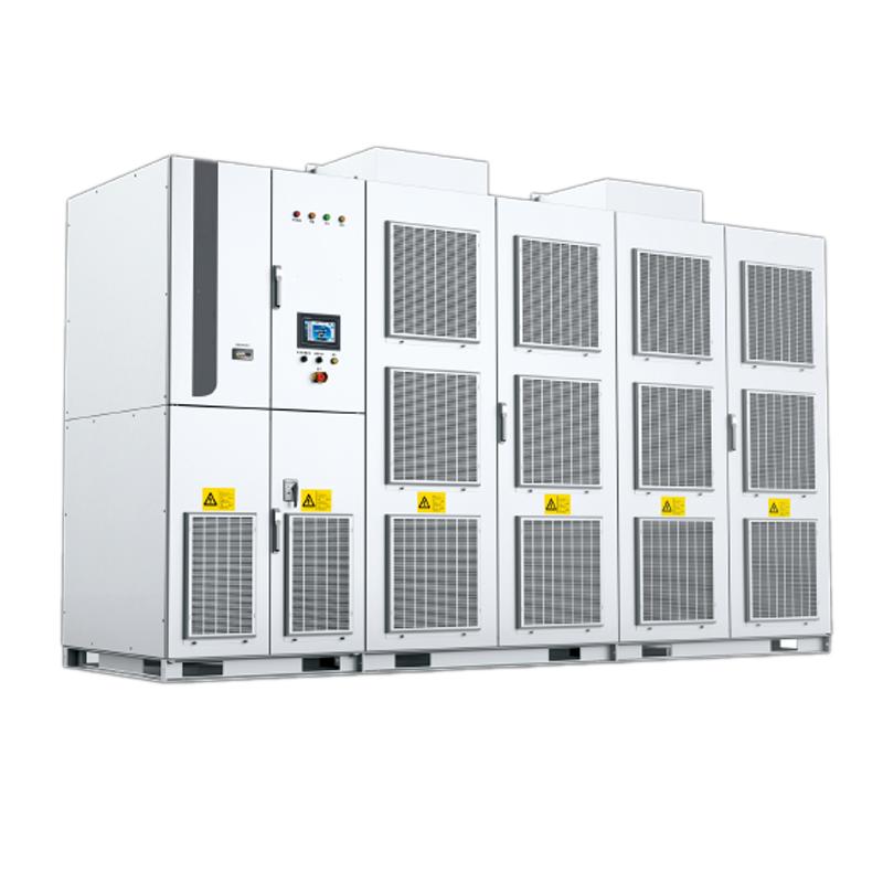
Product Overview
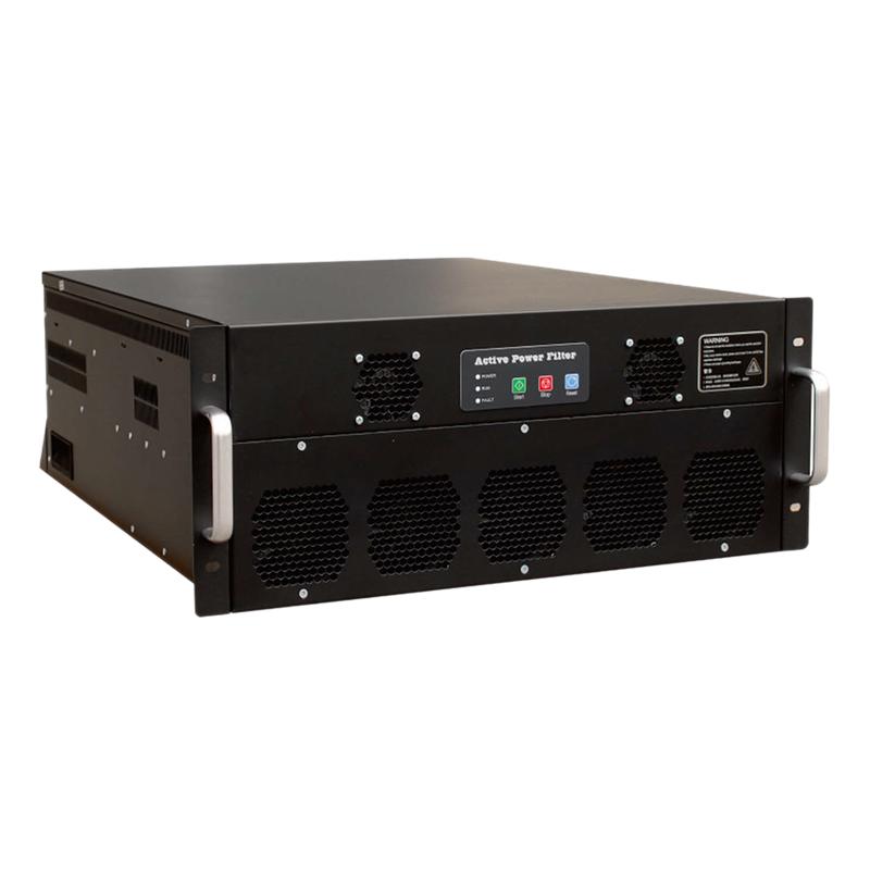
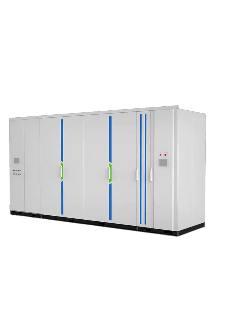
Active Power Filter (APF) is a high-performance power quality optimization device designed specifically for medium and low voltage distribution networks. Its core functions focus on harmonic control and precise reactive power compensation, which can quickly capture and suppress harmonic interference in the power grid, while also taking into account reactive power regulation, effectively improving power quality, reducing line losses, and ensuring safe and stable operation of electrical equipment. As a fully controlled power electronic device, APF adopts advanced detection algorithms and power conversion technology, with fast response speed and high compensation accuracy. It can achieve wideband harmonic suppression without the need for additional filtering components and is suitable for various scenarios with nonlinear loads. It is a core equipment for solving harmonic pollution and improving power grid reliability.
System structure and working principle
Core structure
Detection unit: Integrated high-precision current/voltage detection module, real-time collection of current signals from the power grid and load, precise separation of harmonic components and reactive current through FFT and fast Fourier transform technology, providing data support for compensation control.
Control unit: Equipped with a dual core control system of DSP and FPGA, it has fast computing speed and precise control logic. It is linked with the main circuit module through a high-speed communication bus (RS-485/CAN/Ethernet) to achieve real-time command issuance and status monitoring.
Main circuit module: The bridge inverter circuit is composed of high-performance IGBT power modules, which have strong overload capacity and stable operation characteristics, and can quickly generate compensation current according to control instructions; Equipped with filtering and protection units to achieve current limiting, overvoltage protection, and electromagnetic compatibility.
Auxiliary structure: including dual power supply modules, cooling systems, and protective cabinets to ensure continuous and stable operation of the equipment under complex working conditions.
Working principle
The controller monitors the nonlinear load current in the power grid in real time through the detection unit, uses FFT fast Fourier transform technology to analyze the amplitude and phase information of each harmonic current, and instantly calculates the required reverse compensation current parameters. Subsequently, the switching state of the IGBT module is controlled through PWM pulse width modulation technology to generate compensation current with equal amplitude and opposite phase to the harmonic current, which is accurately injected into the power grid and cancels out the harmonic current generated by the load. At the same time, reactive power can be dynamically adjusted according to demand, ultimately achieving sinusoidal current and power factor optimization in the power grid, significantly reducing harmonic distortion rate (THDi), and ensuring that power quality meets relevant national standards.
Cooling method
Forced cooling (AF/Air Cooling)
Water Cooling
Main Features
Accurate and efficient harmonic suppression: It can suppress 2-50 harmonics, reduce the harmonic distortion rate THDi to below 5%, and achieve a compensation current resolution of 0.1A. It can accurately respond to complex harmonics generated by nonlinear loads such as frequency converters, arc furnaces, rectifiers, etc.
Rapid response and dynamic compensation: With a response time of less than 5ms, it can track the dynamic changes of load harmonics and reactive power in real time without delay compensation, effectively solving the problem of power quality fluctuations caused by impact loads.
Stable and reliable, with strong adaptability: adopting a dual power supply design and redundant protection mechanism, it has multiple protection functions such as overvoltage, undervoltage, overcurrent, overheating, and drive failure; The protection level reaches IP30 (indoor)/IP44 (outdoor), can withstand operating temperatures of -35 ℃~+40 ℃, and is suitable for various harsh working conditions.
Flexible functionality, compatible with expansion: supports separate compensation for harmonics, separate compensation for reactive power, or a combination of both compensation modes; Compatible with multiple communication protocols such as Modbus RTU and IEC61850, it can achieve parallel network operation of multiple machines and meet the requirements of different capacity scenarios.
Energy saving and environmentally friendly, economical and practical: its own power loss is less than 1%, no additional harmonic generation, and does not affect the original structure of the power grid; No need for large capacity capacitors or inductive components, compact structure, saving installation space and initial investment.
Technical Specifications
Name |
specifications |
|
APF |
3-Phase,3-wire |
3-Phase,4-wire |
Rated compensation current |
100A-600A |
50A-600A |
Working voltage |
400V(-20% ~ +15%) 690V(-20% ~ +15%) |
400V(-20% ~ +15%) |
Working frequency(Hz) |
50/60 |
50/60 |
Harmonic compensation range |
2-50 harmonics |
|
Response time |
<10ms |
|
THDI |
<3%(Rated) |
|
Overload |
≤100% |
|
Display |
LCD |
|
Display value |
Current and Voltage |
|
Communication |
Modbus,RS485,TCP/IP,ETH |
|
Working temperature |
-10℃~45℃ |
|
Humidity |
≤90% |
|
Installation site |
Indoor |
|
Altitude |
≤1000m |
|
Application scenarios
Industrial sectors: Steel, metallurgy (electric arc furnaces, continuous casting machines), mining (frequency converter driven equipment), petrochemicals (compressors, pumps), automotive manufacturing (welding equipment, coating lines) and other scenarios with a large number of nonlinear loads, to control harmonic pollution and ensure stable operation of production equipment.
Commercial and civil buildings: central air conditioning, elevators, lighting systems for office buildings, shopping malls, hotels, UPS power supplies for data centers, server clusters, to suppress harmonic interference and avoid damage to electrical equipment.
In the field of new energy, the inverter side of photovoltaic power plants and wind farms is used to control the harmonics generated by inverters, improve the quality of new energy grid connected electricity, and meet grid access standards.
In the field of transportation: electrified railway traction stations, urban rail transit power supply systems, solve the harmonic and negative sequence problems generated by traction loads, and stabilize the power supply voltage.
Other scenarios: medical equipment, precision instrument production lines, airport and port lifting equipment, and other scenarios that require strict power quality, providing a pure power environment.
Capacity selection core: harmonic current calculation+scene correction, specific methods are as follows:
Both are power quality optimization devices, but their functional focus and application scenarios are different:
APF (Active Power Filter): The core function is harmonic control, which can accurately suppress 2-50 harmonics and also has a small amount of reactive power compensation capability. It is suitable for scenarios with severe harmonic pollution (such as frequency converters and rectifier loads), and prioritizes solving the problem of THDi exceeding the standard.
SVG (Static Var Generator): The core function is reactive power compensation, achieving power factor optimization and voltage stability, with harmonic suppression as an auxiliary function. It is suitable for scenarios with large reactive power fluctuations (such as new energy and impact loads), and prioritizes solving low power factor and voltage flicker problems.
Selection core: APF is mainly selected for harmonic exceedance, and SVG is mainly selected for reactive power deficiency and voltage fluctuation. The two can be used together to achieve comprehensive governance of "harmonic+reactive power".