| Brand | Switchgear parts |
| Model NO. | 35kV-1100kV Ultra high voltage pillar composite insulator |
| Rated voltage | 40.5kV |
| 额定弯曲负荷 | 20kN |
| Series | FZSW |
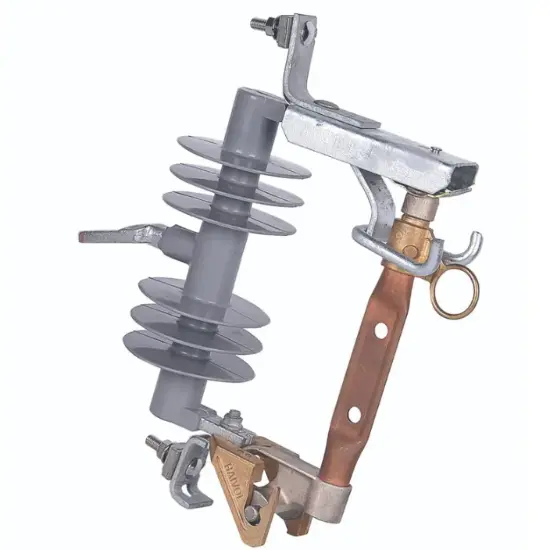
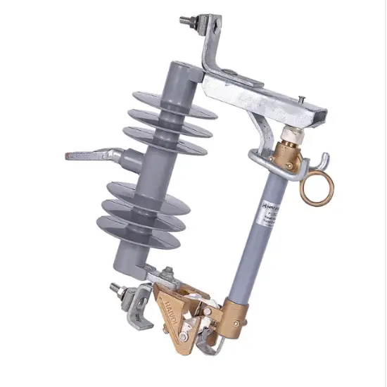
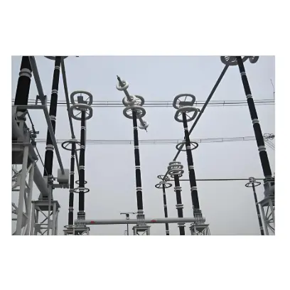
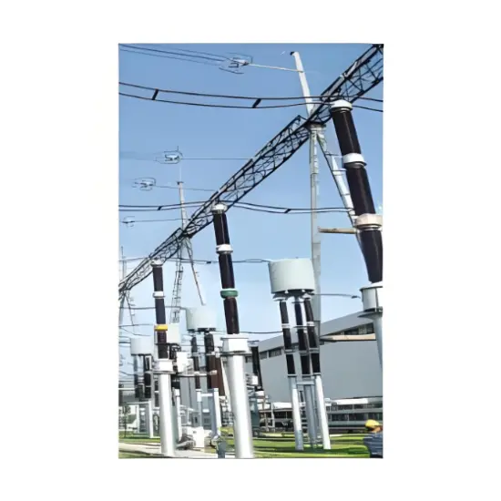
The composite insulator for power system is composed of three main components: core body (FRP), silicone rubber umbrella sleeve (HTV), and end flange (precision cast steel, welded steel, stainless steel). The two end flanges are assembled with the core body by crimping. This product has excellent anti fouling flashover performance, anti brittle fracture, excellent insulation performance, light weight, easy installation and transportation, safety and reliability, and other advantages. Pillar composite insulators are used in electrical equipment such as substations and converter stations with AC voltage ranging from 40.5kV to 1100kV and DC voltage ranging from ± 100kV to ± 800kV. The main application products include reactor supports, high-voltage isolation switch insulation pillars, busbar supports, and insulation supports for other high-voltage equipment.
Product Features
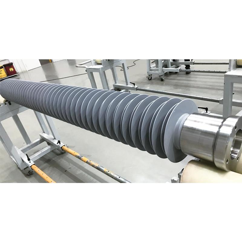
a) Core: Using epoxy resin glass fiber pull rods as internal insulation support, it has excellent seismic performance and can prevent brittle fracture;
b) Silicone rubber umbrella cover: injection molded as a whole, optimized umbrella design, improved crawling distance effectiveness and product pollution flashover voltage;
c) End flange: The flange is assembled using crimping technology, which ensures stable and reliable mechanical performance and high production efficiency;
d) The overall weight of the product is lighter than that of porcelain insulators, making it easier to install, with a short production cycle and high quality stability.
Product Specifications
| Insulator Model | Rated Voltage (kV) | Maximum Operating Voltage (kV) | Mechanical Load (≥) | Structural Height (≥ mm) | Arc Flash Distance (≥ mm) | Minimum Nominal Creepage Distance (≥ mm) | Power Frequency/DC Wet Withstand Voltage (≥ kV) | Lightning Impulse Withstand Voltage (≥ kV) | Switching Impulse Withstand Voltage (≥ kV) | Core Diameter (mm) | Number of Sections | |||
|---|---|---|---|---|---|---|---|---|---|---|---|---|---|---|
| SCL (kN) | SCOL (kN) | STOL (kN·m) | STL (kN) | |||||||||||
| FZSW-40.5/20 | 35 | 40.5 | 20 | 150 | 4 | 50 | 680 | 510 | 1900 | 130 | 250 | / | 90 | 1 |
| FZSW-72.5/15 | 66 | 72.5 | 15 | 150 | 10 | 10 | 850 | 680 | 2600 | 140 | 325 | / | 90 | 1 |
| FZSW-126/8 | 110 | 126 | 8 | 150 | 4 | 100 | 1250 | 1080 | 4300 | 230 | 550 | / | 90 | 1 |
| FZSW-±100/20 | ±100 | ±120 | 20 | 220 | 10 | 100 | 1640 | 1400 | 3500 | ±200 | (650) 350 | / | 110 | 1 |
| FZSW-220/24 | 220 | 252 | 24 | / | 10 | / | 2295 | 2027 | 7040 | 395 | 1050 | / | 110 | 1 |
| FZSW-252/22 | 220 | 252 | 22 | 350 | 10 | 100 | 2400 | 2130 | 9000 | 460 | 1050 | 850 | 120 | 1 |
| FZSW-363/20 | 330 | 363 | 20 | 350 | 10 | 100 | 3000 | 2700 | 10000 | 560 | 1100 | 852 | 150 | 1 |
| FZSW-±300/30 | ±300 | ±306 | 30 | 350 | 10 | 100 | 3280 | 2860 | 7200 | 570/±560 | 1080 | 852 | 160 | 1 |
| FZSW-±400/25 | ±400 | ±480 | 25 | 400 | 10 | 100 | 5600 | 5180 | 14000 | 1050/±620 | 1350 | 1250 | 180 | 1 |
| FZSW-550/16 | 500 | 550 | 16 | 500 | 10 | 100 | 4600 | 4340 | 18900 | 740 | 2250 | 1240 | 180 | 1 |
| FZSW-±660/30 | ±660 | / | 30 | 500 | 10 | 100 | 8000 | 7200 | 37000 | 960 | 2100 | 1425 | 220 | 2 |
| FZSW-±700/30 | ±700 | ±740 | 30 | 400 | 10 | 200 | 9000 | 8240 | 26000 | 1100/±1200 | 2150 | 1800 | 220 | 2 |
| FZSW-±700/12.5 | ±700 | ±740 | 12.5 | 500 | 10 | 100 | 10000 | 9095 | 38700 | 1050 | 2400 | 1550 | 220 | 3 |
| FZSW-±800/16 | ±800 | ±816 | 16 | 500 | 10 | 100 | 12270 | 10675 | 42750 | 1620 | 2750 | 1900 | 280 | 5 |
| FZSW-±1100/16 | ±1100 | / | 16 | 500 | 10 | 100 | 15773 | 13818 | 55000 | / | 2550 | 2100 | 280 | 6 |
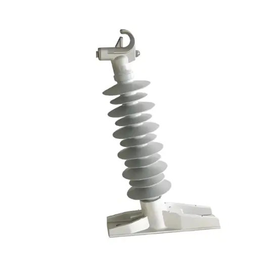
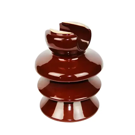
Suitable for 35-110kV substations, overhead transmission lines, switchgear, and railway electrification systems. Core parameters: Rated voltage 35/66/110kV, rated mechanical load ≥10kN, creepage distance 25-31mm/kV (customizable for heavy pollution), operating temperature -40℃~+80℃. Ideal for high-altitude, coastal, industrial heavy pollution, and other harsh environments.
Key advantages include: ① Lightweight (60% lighter than ceramic ones), simplifying transportation and installation; ② Excellent hydrophobicity and self-cleaning performance, avoiding pollution flashover even in heavy pollution areas; ③ Good impact resistance and flexibility, not easy to break; ④ Low maintenance demand, with a service life of over 30 years; ⑤ Environmentally friendly manufacturing process and recyclable materials.
As a key insulation component for power systems, it mainly realizes two core functions: ① Electrical insulation between high-voltage conductors and grounded structures to prevent leakage current; ② Mechanical support for conductors and equipment, ensuring stable operation of 35-110kV substations, power transmission lines, and switchgear under various environmental conditions.