| Brand | Rw Energy |
| Model NO. | 10kV Static Var Generator(SVG) for Power Quality |
| Rated voltage | 10kV |
| Cooling mode | Liquid cooling |
| Range of rated capacity | 16~25 Mvar |
| Series | RSVG |
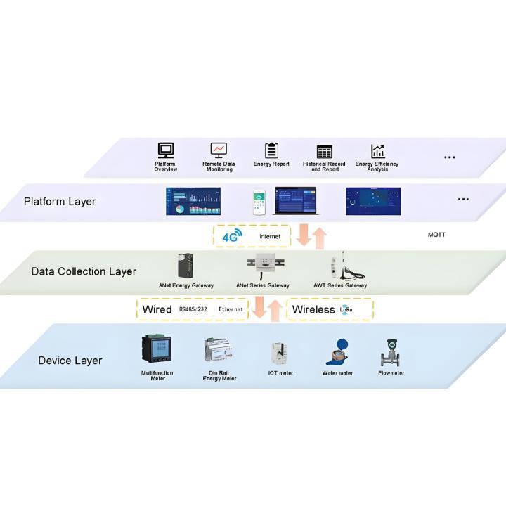
Product overview
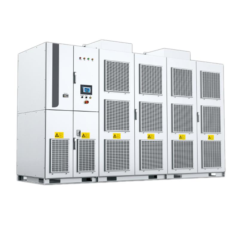
The 10kV direct-mounted high-voltage SVG (Static Var Generator) is an advanced reactive power compensation device for medium and high-voltage distribution networks. Its "direct-mounted" design means the equipment is connected directly to the 10kV grid through cascaded power units, eliminating the need for a step-up transformer. It serves as a key device for improving power quality and enhancing grid stability. The SVG boasts a response time of milliseconds, enabling instantaneous compensation. As a current-source type, its output is less affected by voltage, allowing it to provide robust reactive power support even under low-voltage conditions. The SVG generates almost no low-order harmonics, and the direct-mounted design eliminates transformers, resulting in a compact structure.
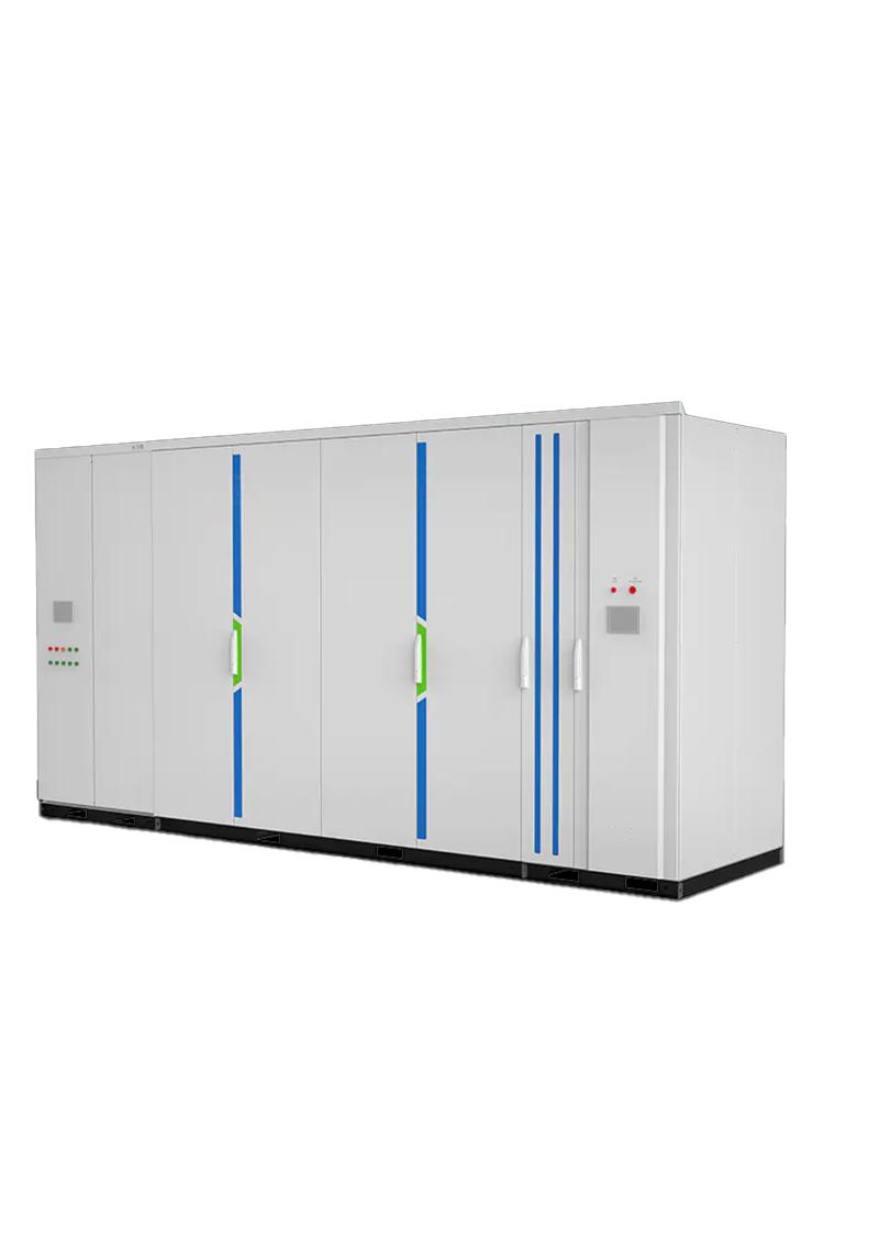
System Structure and Working Principles
Core structure: Power Unit Cabinet: Composed of dozens of 1700V-rated H-bridge IGBT modules connected in series, collectively withstanding 10kV high voltage. It integrates high-speed control (DSP+FPGA) and communicates with all power units via RS-485/CAN bus for state monitoring and command issuance. Grid-side Coupling Transformer: Functions to filter, limit current, and suppress current rate of change.
Working Principle:The controller continuously monitors the grid load current, instantaneously calculates the required reactive current compensation, and controls the switching of IGBTs via PWM technology. This generates a current synchronized with the grid voltage and phase-shifted by 90 degrees, precisely offsetting the load's reactive power. As a result, the grid side supplies only active power, achieving high power factor and voltage stability.
Heat dissipation mode

Mian feature
High Efficiency and Cost-Effectiveness: No transformer losses, system efficiency exceeds 98.5%, while saving on transformer costs and space.
Dynamic Precision: Millisecond-level response, stepless smooth compensation, effectively eliminating voltage flicker caused by impact loads (e.g., arc furnaces, rolling mills).
Stable and reliable: It can still provide robust reactive power support even when grid voltage fluctuates.
Environmentally friendly: It has extremely low harmonic output, causing minimal pollution to the power grid.
Technical Parameters
Name |
Specification |
Rated voltage |
6kV±10%~35kV±10% |
Assessment point voltage |
6kV±10%~35kV±10% |
Input voltage |
0.9~ 1.1pu; LVRT 0pu(150ms), 0.2pu(625ms) |
Frequency |
50/60Hz; Allow short-term fluctuations |
Output capacity |
±0.1Mvar~±200 Mvar |
Starting power |
±0.005Mvar |
Compensation current resolution |
0.5A |
Response time |
<5ms |
Overload capacity |
>120% 1min |
Power loss |
<0.8% |
THDi |
<3% |
Power supply |
Dual power supply |
Control power |
380VAC, 220VAC/220VDC |
Reactive power regulation mode |
Capacitive and inductive automatic continuous smooth adjustment |
Communication interface |
Ethernet, RS485, CAN, Optical fiber |
Communication protocol |
Modbus-RTU, Profibus, CDT91, IEC61850- 103/104 |
Running mode |
Constant device reactive power mode, constant assessment point reactive power mode, constant assessment point power factor mode, constant assessment point voltage mode and load compensation mode |
Parallel mode |
Multi machine parallel networking operation, multi bus comprehensive compensation and multi group FC comprehensive compensation control |
Protection |
Cell DC overvoltage, Cell DC undervoltage, SVG overcurrent, drive fault, power unit overvoltage, overcurrent, overtemperature and communication fault; Protection input interface, protection output interface, abnormal system power supply and other protection functions. |
Fault handling |
Adopt redundant design to meet N-2 operation |
Cooling mode |
Water cooling/Air cooling |
IP degree |
IP30(indoor); IP44(outdoor) |
Storage temperature |
-40℃~+70℃ |
Running temperature |
-35℃~ +40℃ |
Humidity |
<90% (25℃), no condensation |
Altitude |
<=2000m (above 2000m customized) |
Earthquake intensity |
Ⅷ degree |
Pollution level |
Grade IV |
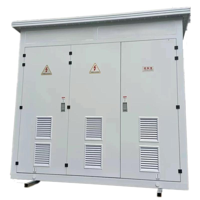
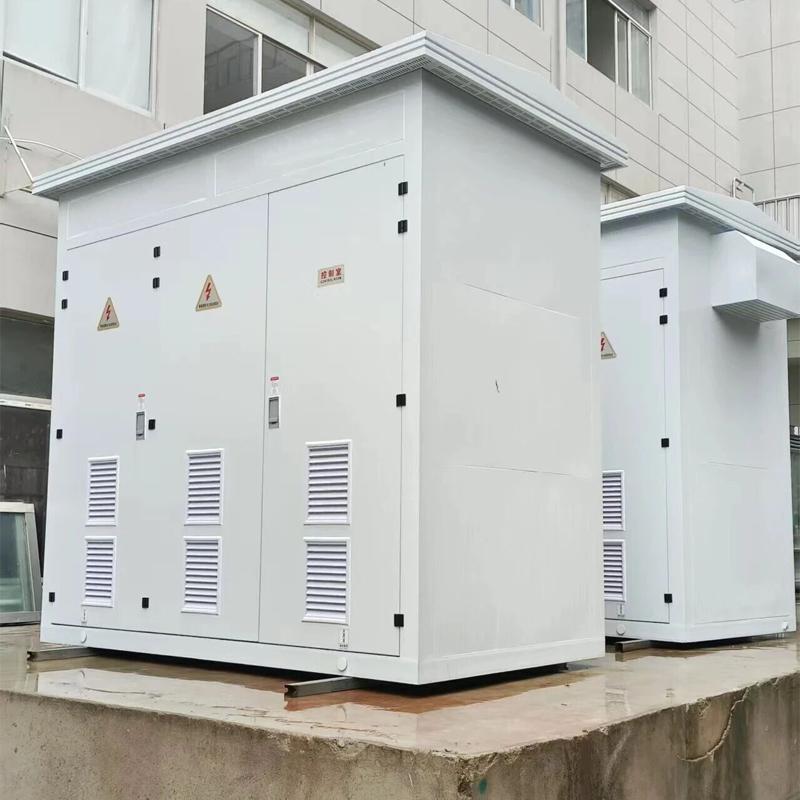
Specifications and dimensions of 10kV outdoor products
Air cooling type
| Voltage class(kV) | Rated capacity(Mvar) | Dimension W*D*H(mm) |
Weight(kg) | Reactor type |
| 10 | 0.5~0.9 | 3200*2350*2591 | 3000 | Iron core reactor |
| 1.0~4.0 | 5500*2350*2800 | 6500~6950 | Iron core reactor | |
| 5.0~6.0 | 5500*2350*2800 | 6700~6950 | Iron core reactor | |
| 7.0~12.0 | 6700*2438*2560 | 6700~6950 | Air core reactor | |
| 13.0~21.0 | 9700*2438*2560 | 9000~9700 | Air core reactor |
Water cooling type
| Voltage class(kV) | Rated capacity(Mvar) | Dimension W*D*H(mm) |
Weight(kg) | Reactor type |
| 10 | 1.0~15.0 | 5800*2438*2591 | 8200~9200 | Air core reactor |
| 16.0~25.0 | 9300*2438*2591 | 13000~15000 | Air core reactor |
Note:
1. Capacity (Mvar) refers to the rated regulation capacity within the dynamic regulation range from inductive reactive power to capacitive reactive power.
2. The air core reactor is used for the equipment, and there is no cabinet, so the placement space needs to be planned separately.
3. The above dimensions are for reference only. The company reserves the right to upgrade and improve the products. The product dimensions are subject to change without notice.
Application Scenarios
New Energy Power Stations (Wind/Solar): Mitigate power fluctuations and ensure grid-connected voltage stability meets standards.
Heavy Industry (Steel/Mining/Port): Compensate for impact loads such as electric arc furnaces, large rolling mills, and hoists.
Electrified railways: Addressing negative sequence and reactive power issues in the traction power supply system.
SVG capacity selection core: steady-state calculation & dynamic correction. Basic formula: Q ₙ=P × [√ (1/cos ² π₁ -1) - √ (1/cos ² π₂ -1)] (P is active power, power factor before compensation, target value of π₂, often requires ≥ 0.95). Load correction: impact/new energy load x 1.2-1.5, steady-state load x 1.0-1.1; High altitude/high temperature environment x 1.1-1.2. New energy projects must comply with standards such as IEC 61921 and ANSI 1547, with an additional 20% low-voltage ride through capacity reserved. It is recommended to leave 10% -20% expansion space for modular models to avoid compensation failure or compliance risks caused by insufficient capacity.
What are the differences between SVG, SVC, and capacitor cabinets?
The three are the mainstream solutions for reactive power compensation, with significant differences in technology and applicable scenarios:
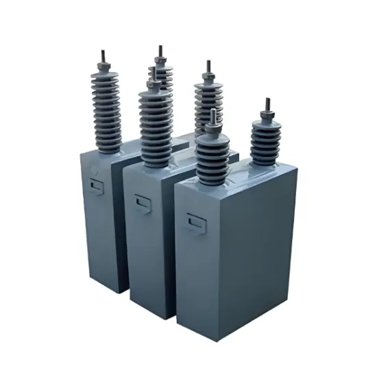
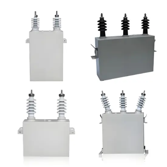
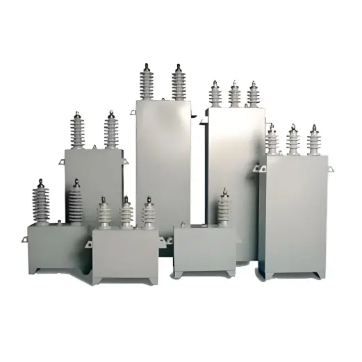
Capacitor cabinet (passive): The lowest cost, graded switching (response 200-500ms), suitable for steady-state loads, requires additional filtering to prevent harmonics, suitable for budget limited small and medium-sized customers and entry-level scenarios in emerging markets, in compliance with IEC 60871.
SVC (Semi Controlled Hybrid): Medium cost, continuous regulation (response 20-40ms), suitable for moderate fluctuating loads, with a small amount of harmonics, suitable for traditional industrial transformation, in compliance with IEC 61921.
SVG (Fully Controlled Active): High cost but excellent performance, fast response (≤ 5ms), high-precision stepless compensation, strong low-voltage ride through capability, suitable for impact/new energy loads, low harmonic, compact design, in line with CE/UL/KEMA, is the preferred choice for high-end markets and new energy projects.
Selection core: Choose capacitor cabinet for steady-state load, SVC for moderate fluctuation, SVG for dynamic/high-end demand, all of which need to match international standards such as IEC.