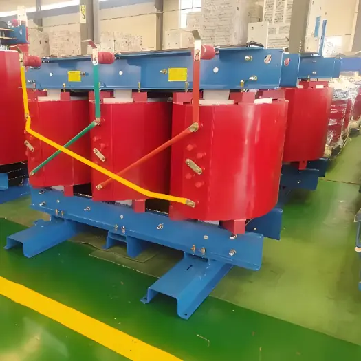
• Product
  • Suppliers
  • Manufacturers
  • Solutions
  • Free tools
  • Knowledges
  • Experts
  • Communities
Search


100kVA Step Up All Copper Three Phase Dry Type Distribution Transformer

  • 100kVA Step Up All Copper Three Phase Dry Type Distribution Transformer
  • 100kVA Step Up All Copper Three Phase Dry Type Distribution Transformer

Key attributes

Brand Vziman
Model NO. 100KVA Step Up All Copper Three Phase Dry Type Distribution Transformer
Rated capacity 100kVA
Voltage grade 20KV
Series SC(B)

Product descriptions from the supplier

Description

Description:

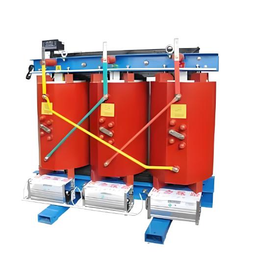
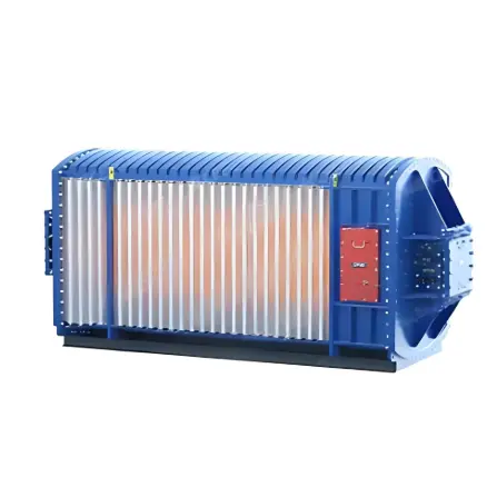
  • Dry-type transformers rely on natural or forced air cooling to dissipate the heat generated during operation. Proper ventilation and airflow around the transformer are essential to prevent overheating and maintain optimal efficiency.

  • Dry-type transformers are less susceptible to environmental factors than oil-immersed transformers, but certain environmental conditions still need to be taken into account.

  • The installation site should have protection against exposure to moisture, dust, corrosive agents, or other contaminants that could potentially degrade the transformer's insulation and components.

  • In harsh environments, such as coastal areas or industrial settings, additional protection measures, such as weatherproof enclosures or specialized coatings, may be necessary.

  • Proper electrical connections, including the primary and secondary windings, as well as the grounding of the transformer, must be carried out according to relevant electrical codes and manufacturer's specifications.

Feature:


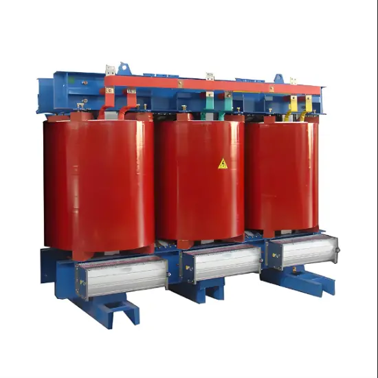
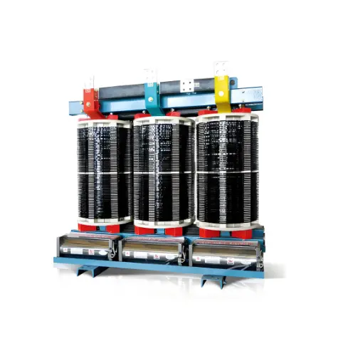
  • The magnetic core has a miter step joint to ensure optimum performance and minimum sound levels by using step lap technology.

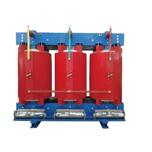
  • Windings are cast under vacuum with epoxy resin. Transient analysis tests have been performed to verify the electrical stress distribution.

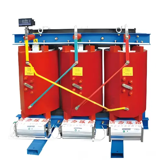
  • Air-cooling system adopts top-blowing cross flow fan, which has the characteristics of low noise, high wind pressure, beautiful look, etc.

  • Intelligent temperature controller improves the safety and reliability of the transformer.

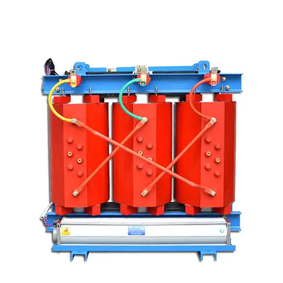
  • Supply various Enclosure options in IP20, IP23, etc.


Parameter:

image.png

Installation Location:


  • Installed in places without fire, explosion hazard, serious pollution, chemical corrosion and cluster vibration, indoor or outdoor.

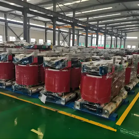
  • Supply Ability:500 Set/Sets per Month.

Customized Service:

  • E2 Environmental Class.

  • C2 Climate Class.

  • F1 Fire Resistance Class.

Product Advantages:

  •  Vacuum-Casting

  • Our product is manufactured with vacuum casting process using a metal pattern, producing a thick resin layer with a smooth surface.

  •  Partial Discharge Free

  • Lower partial discharge characteristics.

  • All units are subjected to partial discharge test.

  • Voltage that is twice that of the operating system is applied to ensure safety.

  • Partial discharge is less than 10 pC.

  •  Shop Test Items.

Routine test:

  • Routine test is a must test for all transformers in our workshop.

  • Type test (as requested).

  • Lightning impulse test.

  • Temperature-rise test.

  • Measurement of sound level.


What is a step-up all-copper three-phase dry-type distribution transformer?

Definitions and Characteristics:

  • Voltage Boosting: It means that a transformer converts the input low-voltage electrical energy into high-voltage electrical energy.

  • All-Copper: The windings of the transformer are all made of copper wires, which possess excellent electrical conductivity and mechanical strength.

  • Three-Phase: It indicates that the transformer has three independent windings and is applicable to three-phase alternating current systems.

  • Dry-Type: It means that the transformer does not use a liquid cooling medium (such as transformer oil), and usually adopts natural air cooling or forced air cooling.

Working Principle:

  • Input Voltage: The low-voltage power source is applied to the transformer through the primary winding.

  • Generating Magnetic Field: The current in the primary winding generates an alternating magnetic field in the iron core.

  • Transferring Magnetic Field: The alternating magnetic field is transferred to the secondary winding through the iron core.

  • Inducing Electromotive Force: The alternating magnetic field induces an electromotive force in the secondary winding, generating a high-voltage output voltage.

  • Output Voltage: The secondary winding outputs the required high-voltage electrical energy for the load to use.


Documentation Resource Library
Restricted
Vziman IEC/ ANSI Dry-Type Power transformer selection catalog
Catalogue
English
Consulting
Consulting
Know your supplier
Online store
On-time delivery rate
Response time
100.0%
≤4h
Company overview
Workplace: 10000m² Total staff: Highest Annual Export(usD): 150000000
Workplace: 10000m²
Total staff:
Highest Annual Export(usD): 150000000
Services
Business Type: Design/Manufacture/Sales
Main Categories: High Voltage Electrical Apparatus/Electric transformer
Whole life care manager
Whole-life care management services for equipment procurement, use, maintenance, and after-sales, ensuring safe operation of electrical equipment, continuous control, and worry-free electricity consumption.
The equipment supplier has passed platform qualification certification and technical evaluation, ensuring compliance, professionalism, and reliability from the source.

Related Products

Related Knowledges

  • Impact of DC Bias in Transformers at Renewable Energy Stations Near UHVDC Grounding Electrodes
    Impact of DC Bias in Transformers at Renewable Energy Stations Near UHVDC Grounding ElectrodesWhen the grounding electrode of an Ultra-High-Voltage Direct Current (UHVDC) transmission system is located close to a renewable energy power station, the return current flowing through the earth can cause a rise in ground potential around the electrode area. This ground potential rise leads to a shift in the neutral-point potential of nearby power transformers, inducing DC bias (or DC offset) in their
    01/15/2026
  • HECI GCB for Generators – Fast SF6 Circuit Breaker
    1.Definition and Function1.1 Role of the Generator Circuit BreakerThe Generator Circuit Breaker (GCB) is a controllable disconnect point located between the generator and the step-up transformer, serving as an interface between the generator and the power grid. Its primary functions include isolating generator-side faults and enabling operational control during generator synchronization and grid connection. The operating principle of a GCB is not significantly different from that of a standard c
    01/06/2026
  • Distribution Equipment Transformer Testing, Inspection, and Maintenance
    1.Transformer Maintenance and Inspection Open the low-voltage (LV) circuit breaker of the transformer under maintenance, remove the control power fuse, and hang a “Do Not Close” warning sign on the switch handle. Open the high-voltage (HV) circuit breaker of the transformer under maintenance, close the grounding switch, fully discharge the transformer, lock the HV switchgear, and hang a “Do Not Close” warning sign on the switch handle. For dry-type transformer maintenance: first clean the porcel
    12/25/2025
  • How to Test Insulation Resistance of Distribution Transformers
    In practical work, insulation resistance of distribution transformers is generally measured twice: the insulation resistance between thehigh-voltage (HV) windingand thelow-voltage (LV) winding plus the transformer tank, and the insulation resistance between theLV windingand theHV winding plus the transformer tank.If both measurements yield acceptable values, it indicates that the insulation among the HV winding, LV winding, and transformer tank is qualified. If either measurement fails, pairwise
    12/25/2025
  • Design Principles for Pole-Mounted Distribution Transformers
    Design Principles for Pole-Mounted Distribution Transformers(1) Location and Layout PrinciplesPole-mounted transformer platforms should be located near the load center or close to critical loads, following the principle of “small capacity, multiple locations” to facilitate equipment replacement and maintenance. For residential power supply, three-phase transformers may be installed nearby based on current demand and future growth projections.(2) Capacity Selection for Three-Phase Pole-Mounted Tr
    12/25/2025
  • Transformer Noise Control Solutions for Different Installations
    1.Noise Mitigation for Ground-Level Independent Transformer RoomsMitigation Strategy:First, conduct a power-off inspection and maintenance of the transformer, including replacing aged insulating oil, checking and tightening all fasteners, and cleaning dust from the unit.Second, reinforce the transformer foundation or install vibration isolation devices—such as rubber pads or spring isolators—selected based on the severity of vibration.Finally, strengthen sound insulation at weak points of the ro
    12/25/2025

Related Solutions

  • Choosing Vizman Distribution Transformers: Innovative Customization to Meet Diverse Power Needs
    Distribution transformers are the heart of local electricity distribution systems. They step down voltage, enabling safe and efficient power supply to homes and businesses.At Vizman Electric Power Technology Co., Ltd., we understand the critical role of distribution transformers in the energy ecosystem. That's why we specialize in manufacturing high-quality distribution transformers, providing tailored solutions to meet diverse energy needs.1.Solutions Offered by Vizman Electric Power Technology
    04/16/2025
  • SF6 Circuit Breaker Solutions in High-Voltage Power Systems: A Case Study of VZIMAN Company
    ​1. Challenges in High-Voltage Power Systems​1.1 High-voltage power systems, as the core of power transmission, face critical challenges:​Equipment Performance Limits: With increasing voltage levels (e.g., 500kV and above), traditional circuit breakers struggle to meet high breaking capacities (over 40kA) and rapid insulation recovery requirements.​Overvoltage Risks: Switching capacitive loads (e.g., capacitor banks) may cause reignition, leading to dangerous overvoltages.​Poor Environmental Ada
    05/13/2025
  • VZIMAN Company SF6 Circuit Breaker Solutions for Renewable Energy Grid Integration
    1. Current Challenges in Renewable Energy Grid Integration1.1 ​Grid Frequency Fluctuations and Stability Issues​The intermittency and variability of renewable energy sources (e.g., wind and solar) lead to frequent grid frequency changes. Traditional circuit breakers struggle to respond rapidly to such dynamic loads, potentially causing equipment damage or regional blackouts. For instance, during sudden drops in wind power or abrupt solar output fluctuations, the grid must isolate faults within m
    05/13/2025
Related Free tools
Haven't found the right supplier yet? Let matching verified suppliers find you. Get Quotation Now
Haven't found the right supplier yet? Let matching verified suppliers find you.
Get Quotation Now
Send inquiry
+86
Click to upload file

IEE Business will not sell or share your personal information.

Download
Get the IEE Business Application
Use the IEE-Business app to find equipment, obtain solutions, connect with experts, and participate in industry collaboration anytime, anywhere—fully supporting the development of your power projects and business.