• Product
  • Suppliers
  • Manufacturers
  • Solutions
  • Free tools
  • Knowledges
  • Experts
  • Communities
Search


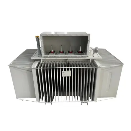
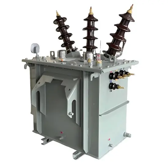
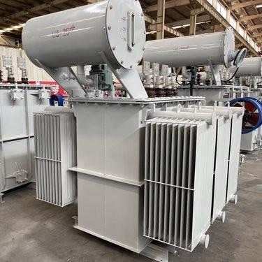
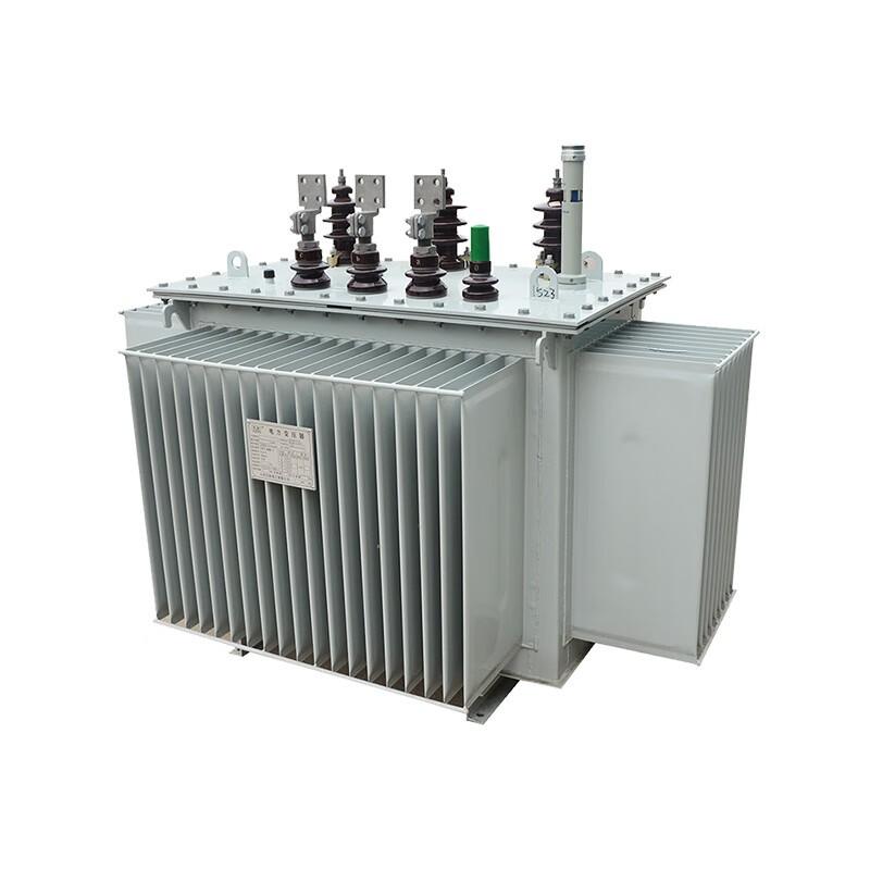
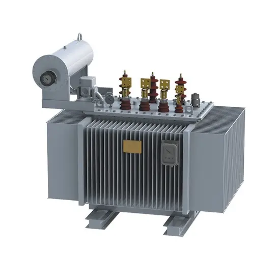
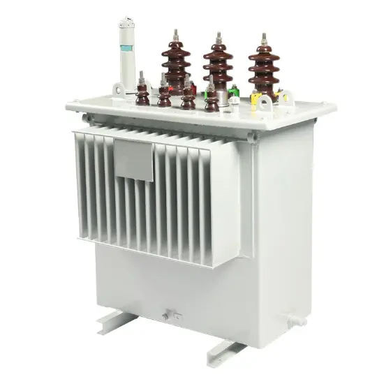
Three-phase Oil-immersed distribution transformer 1000kVA 11kV

  • Three-phase Oil-immersed distribution transformer 1000kVA 11kV
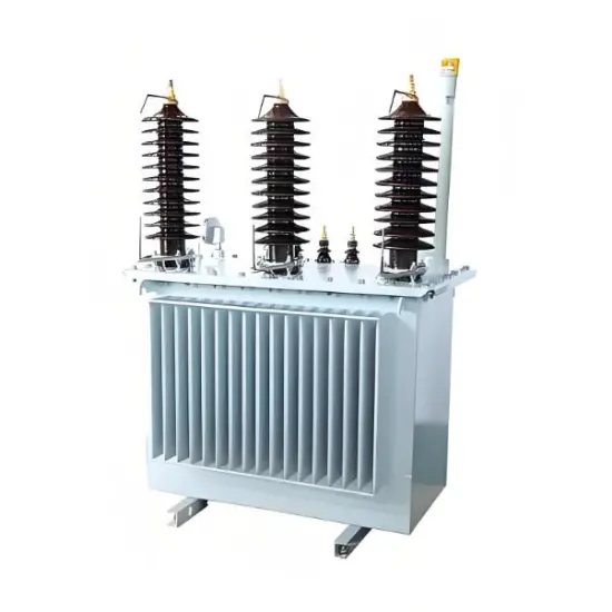
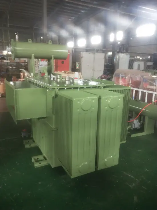
  • Three-phase Oil-immersed distribution transformer 1000kVA 11kV
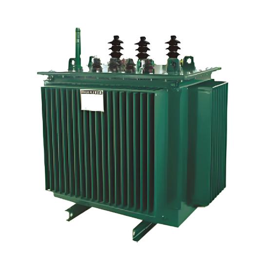
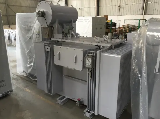
  • Three-phase Oil-immersed distribution transformer 1000kVA 11kV

Key attributes

Brand Vziman
Model NO. Three-phase Oil-immersed distribution transformer 1000kVA 11kV
Rated voltage 11kV
Rated capacity 1000kVA
Series S
Description

Description

This Oil-immersed distribution transformer adopts our professional calculation and strict validation procedures to guarantee stable performance of the distribution transformer. Supported by advanced processing equipment, premium material selection and standardized production flow, the Oil-immersed distribution transformer features compact size, light weight, low loss, low partial discharge and low noise.

With stable operation, high reliability, cost efficiency and eco-friendly performance, this distribution transformer is widely applicable. The Oil-immersed distribution transformer is suitable for power plants, transformer substations, large industrial mining zones and petrochemical enterprises, delivering steady power conversion and distribution for various power system projects.

Features

  • Ultralow no-load loss for the Oil-immersed distribution transformer.

  • Excellent energy saving performance and high power efficiency of the distribution transformer.

  • Pure copper coil winding endows the Oil-immersed distribution transformer with strong short-circuit withstand capability.

  • Dyn11 connection mode effectively reduces harmonic interference for the distribution transformer.

  • Fully sealed structure makes the Oil-immersed distribution transformer maintenance-free.

  • Slow insulation aging extends the service life of the distribution transformer.

Parameters

Oil-immersed distribution transformer three-phase

Model NO.

S-1000-11

Product classification

Distribution transformer

Rated capacity

1000kVA

Primary voltage

11kV

Secondary voltage

0.4kV

Number of phase

3

Number of winding

2

Rated frequency

50Hz

Tap changer

OCTC

Tap range

±2×2.5%

Vector group

Dyn11

Cooling system

ONAN

No-load loss

1950+10%

Load loss

9500+10%

Standard

IEC60076

Impedance

4%

Basic insulation level

75/28KV

Winding material ( H.V & L.V)

Copper

The way the bushing appears

Porcelain

Power frequency withstand voltage

——

Lightning impulse

——

The temperature rise—Winding

55k

The temperature rise --Top oil

65k

Tank color

——

Creepage distance

——

Environmental requirement

——

Transformer structure

——

External dimensions

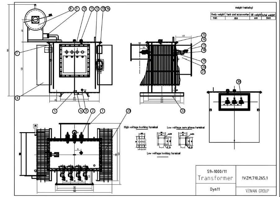
企业微信截图_1724029055640.png

Size

1980mm×1520mm×1885mm

Weight

1585KG

Environmental requirement

Max. ambient temperature


Altitude


Additional Application Scenario

The Oil-immersed distribution transformer and distribution transformer are also widely used in urban and rural grid renovation, residential communities, commercial parks and new energy power stations, providing safe and reliable power distribution support for municipal construction and distributed power supply projects.


Product show


Yawei 160kVA 10kv Hot Selling Oil-Filled Three-Phase Distribution Transformer with UL


What is no-load loss?

No - load loss, also known as iron loss or no - load iron loss, refers to the electrical energy consumed by a transformer in a no - load state (that is, the secondary winding is open - circuited and there is no load current). This part of the loss mainly occurs in the iron core of the transformer and is an inevitable part of energy loss during the operation of the transformer. Understanding no - load loss is of great significance for evaluating the efficiency of a transformer and selecting an appropriate one. The following is a detailed explanation of no - load loss:

1. Definition

No - load loss refers to the loss generated in the iron core when the transformer is in a no - load state, that is, when the secondary winding is open - circuited, and the primary winding is still connected to the power supply. These losses mainly consist of the following two parts:

  • Hysteresis loss: The loss caused by the hysteresis effect of the iron core material.

  • Eddy - current loss: The loss caused by eddy currents in the iron core.
 

Know your supplier

Online store
On-time delivery rate
Response time
100.0%
≤4h
Company overview
Workplace: 10000m² Total staff: 300 Highest Annual Export(usD): 150000000
Services
Business Type: Design/Manufacture/Sales
Main Categories: High Voltage Electrical Apparatus/Electric transformer
Related Products
Related Knowledges
  • Micro-Mechanism Analysis of Distribution Transformer Losses and Technical Pathway Selection under the New GB 20052-2024 Energy Efficiency Standard.
    1. Core Logic: Deep Decomposition of Loss MechanismsDistribution transformer losses are primarily categorized into No-load loss (P0P0​) and Load loss (PkPk​). To achieve a leap in energy efficiency (e.g., from Grade 3 to Grade 1), one must start with micro-mechanisms.1.1 No-load Loss (P0P0​): Hysteresis and Eddy CurrentsNo-load loss is proportional to the square of the magnetic flux density (B2B2) and the frequency (ff) to the power of 1.3–2.5.Hysteresis Loss:Caused by the friction of magn
    04/24/2026
  • Distribution Equipment Transformer Testing, Inspection, and Maintenance
    1.Transformer Maintenance and Inspection Open the low-voltage (LV) circuit breaker of the transformer under maintenance, remove the control power fuse, and hang a “Do Not Close” warning sign on the switch handle. Open the high-voltage (HV) circuit breaker of the transformer under maintenance, close the grounding switch, fully discharge the transformer, lock the HV switchgear, and hang a “Do Not Close” warning sign on the switch handle. For dry-type transformer maintenance: first clean the porcel
    12/25/2025
  • How to Test Insulation Resistance of Distribution Transformers
    In practical work, insulation resistance of distribution transformers is generally measured twice: the insulation resistance between thehigh-voltage (HV) windingand thelow-voltage (LV) winding plus the transformer tank, and the insulation resistance between theLV windingand theHV winding plus the transformer tank.If both measurements yield acceptable values, it indicates that the insulation among the HV winding, LV winding, and transformer tank is qualified. If either measurement fails, pairwise
    12/25/2025
  • Design Principles for Pole-Mounted Distribution Transformers
    Design Principles for Pole-Mounted Distribution Transformers(1) Location and Layout PrinciplesPole-mounted transformer platforms should be located near the load center or close to critical loads, following the principle of “small capacity, multiple locations” to facilitate equipment replacement and maintenance. For residential power supply, three-phase transformers may be installed nearby based on current demand and future growth projections.(2) Capacity Selection for Three-Phase Pole-Mounted Tr
    12/25/2025
  • Risk Identification and Control Measures for Distribution Transformer Replacement Work
    1.Electric Shock Risk Prevention and ControlAccording to typical design standards for distribution network upgrades, the distance between the transformer’s drop-out fuse and the high-voltage terminal is 1.5 meters. If a crane is used for replacement, it is often impossible to maintain the required minimum safety clearance of 2 meters between the crane boom, lifting gear, slings, wire ropes, and the 10 kV live parts, posing a severe risk of electric shock.Control Measures:Measure 1:De-energize th
    12/25/2025
  • Analysis of Common Faults and Causes in Routine Inspection of Distribution Transformers
    Common Faults and Causes in Routine Inspection of Distribution TransformersAs the terminal component of power transmission and distribution systems, distribution transformers play a critical role in supplying reliable electricity to end users. However, many users have limited knowledge of power equipment, and routine maintenance is often carried out without professional support. If any of the following conditions are observed during transformer operation, immediate action should be taken: Excess
    12/24/2025
Related Free tools
Send inquiry
+86
Click to upload file
Download
Get the IEE Business Application
Use the IEE-Business app to find equipment, obtain solutions, connect with experts, and participate in industry collaboration anytime, anywhere—fully supporting the development of your power projects and business.