| Brand | Rw Energy |
| Model NO. | 0.4kV Low voltage Static Var Generator (SVG) |
| Rated voltage | 380V |
| Mounting type | rackmounting |
| Range of rated capacity | 500Mvar |
| Series | RLSVG |
Product Overview
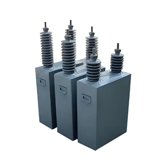
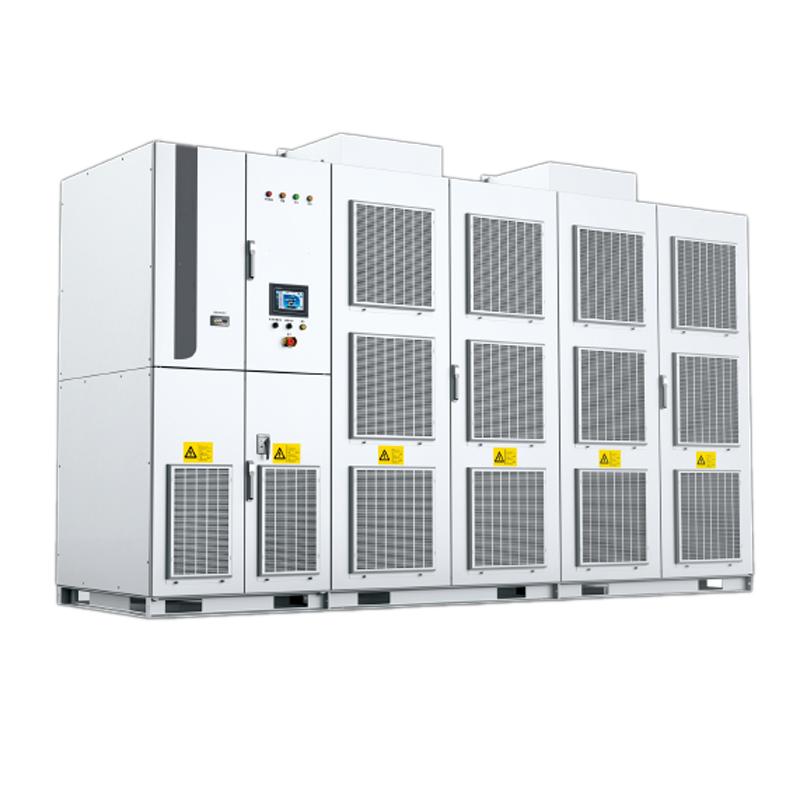
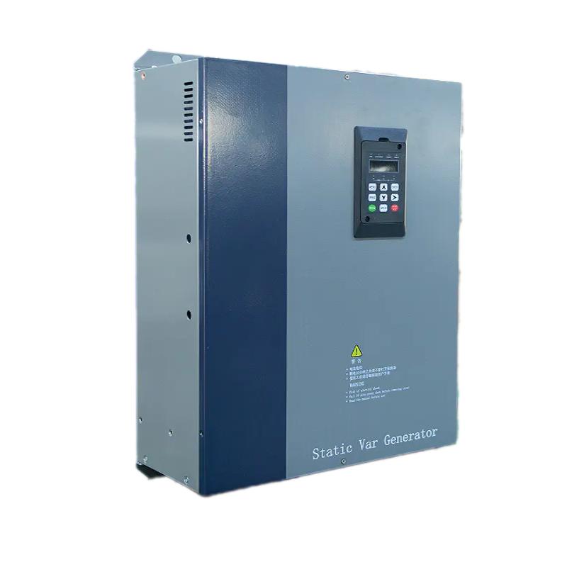
Low voltage Static Var Generator (SVG) is a high-end reactive power compensation device for medium and low voltage distribution networks. It adopts fully controlled power electronics technology and has the core advantage of "direct connection without transformer" design. It can seamlessly integrate into the low-voltage power supply system without the need for additional boosting or lowering devices. As a current source type compensation device, its output performance is minimally affected by voltage fluctuations in the power grid, and it can still provide stable and strong reactive power support even under low voltage conditions. The response speed of the equipment is as fast as milliseconds, which can achieve instantaneous reactive power compensation, effectively suppress voltage flicker, balance three-phase current, and improve power factor; At the same time, it hardly generates low order harmonics, has a compact and small structure, and can save installation space to the greatest extent possible. It is the core equipment for improving the power quality of low-voltage distribution networks and ensuring stable operation of the power grid.
System structure and working principle
Core structure
Power unit cabinet: composed of multiple sets of high-performance low-voltage IGBT modules forming an H-bridge topology structure, adapted to the needs of low-voltage power grids through series or parallel connection. Integrated DSP+FPGA dual core high-speed control system, utilizing RS-485/CAN bus to achieve real-time communication with all power units, accurately completing status monitoring and instruction issuance, ensuring coordinated operation of equipment.
Grid side coupling reactor: It has multiple functions of filtering, current limiting, and suppressing current change rate, effectively blocking the mutual interference between grid harmonics and equipment output side, ensuring the stability and purity of compensation current.
Working principle
The device controller collects real-time load current signals from the power grid, instantly separates active current and reactive current through precise algorithms, and calculates the reactive current component that needs to be compensated. Subsequently, PWM (Pulse Width Modulation) technology is used to control the high-speed switching of IGBT modules, generating a compensation current that is at the same frequency as the grid voltage but 90° ° out of phase, and offsetting the reactive current generated by the load. Ultimately, only active power is transmitted on the grid side, achieving the core goals of power factor optimization and voltage stability, and fundamentally solving the problem of reactive power loss in low-voltage distribution networks.
Installation method
The device provides two installation methods to adapt to different usage environments and working conditions:
Wall mounted: The device is designed to be directly fixed to the wall (or specific bracket) without the need for a separate cabinet, with the core features of "saving floor space and lightweight deployment",
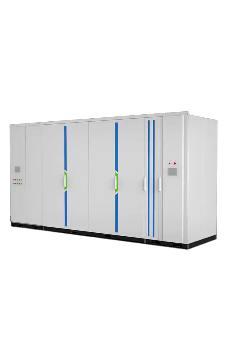
Rack mounted: relying on cabinets to provide unified physical support, heat dissipation, protection, and management, it is more "standardized, scalable, and centralized", making it convenient for centralized and unified management of equipment when deploying multiple units.
Mian Features
Efficient and energy-saving, with excellent cost-effectiveness: no transformer losses, system operating efficiency exceeds 98.5%, significantly reducing energy loss; Save the cost of transformer procurement and installation, while the compact structure saves floor space, with significant comprehensive cost-effectiveness advantages.
Dynamic precision, compensation without dead corners: millisecond level response speed, achieving stepless smooth compensation, can accurately respond to reactive power fluctuations caused by low-voltage impact loads such as arc furnaces, welding machines, and frequency converters, completely eliminating voltage flicker and three-phase imbalance problems.
Stable, reliable, and highly adaptable: It has excellent low-voltage ride through capability, and can continue to provide stable reactive power support even if the grid voltage fluctuates; The whole machine adopts high reliability components and redundant design, with strong anti-interference ability and long service life.
Green and environmentally friendly, with low harmonic pollution: Advanced PWM control technology is adopted, and the output current harmonic content (THDi) is less than 3%, far superior to industry standards. It has almost no harmonic pollution to the power grid and meets the requirements of green power development.
Intelligent control, easy operation: supports multiple operating modes and communication protocols, and can achieve unmanned automatic operation; Equipped with a user-friendly interface, parameter settings, status monitoring, and fault inquiry are intuitive and easy to understand.
Technical parameters
Product function |
Compensate reactive power, control harmonics, balance negative sequence current |
|
Input |
Input voltage |
380VAC±10% |
Frequency |
50±0.2Hz |
|
Cable inlet |
Outdoor: bottom in; Indoor: top in |
|
Grid phase sequence adaptation |
Yes |
|
External CT demand |
Three phase current CT, secondary side rated current 5A, accuracy 0.2S or higher |
|
Current detection mode |
Grid side / load side detection |
|
Performance |
Singe unit capacity |
50-1000 Mvar |
Reactive power output range |
Stepless smooth adjustable from capacitive rated power to inductive rated power |
|
Reactive power output characteristics |
Current source |
|
Response time |
Instantaneous response time: <100US |
|
Special feature |
Fault reset and auto restart |
|
Noise level |
<60dB |
|
Efficiency |
>97% with full load |
|
Display and communication |
Display unit |
FGI HMI |
Communication interface |
RS485 |
|
Communication protocol |
Modbus RTU, IEC60870-5-104 |
|
Protection |
AC over voltage |
Yes |
DC over voltage |
Yes |
|
Over heat |
Yes |
|
Short circuit |
Yes |
|
Over load |
Rated load |
|
Safety performance |
Reliable grounding |
Yes |
Insulation resistance |
500VDC mega meter 100Mohm |
|
Insulation strength |
50Hz, 2.2kV AC voltage for 1min, without breakdown and arcing, and the residual current is less than 10mA |
|
Structure |
Single unit running |
Yes |
Parallel running |
Max 10 units in parallel |
|
IP degree |
Indoor IP20; Outdoor IP44 |
|
Body color |
RAL7035 standard; others customized |
|
Environment |
Environment temperature |
-10~40℃ |
Storage temperature |
-30~70℃ |
|
Humidity |
Less than 90%, no condensation |
|
Altitude |
Less than 2000m |
|
Earthquake intensity |
VIII |
|
Pollution level |
IV |
|
400V indoor product specification and size
Wall mounting type
Voltage |
Rated capacity |
Installation dimension |
Overall dimension |
Hole size R(mm) |
Weight |
|||
W1 |
H1 |
W |
D |
H |
||||
0.4 |
30 |
300 |
505 |
405 |
179 |
465 |
6 |
27.5 |
50 |
300 |
600 |
430 |
200 |
560 |
36.5 |
||
100 |
360 |
650 |
506 |
217 |
610 |
56 |
||
Cabinet type
Voltage |
Rated capacity |
Overall dimension |
Weight |
Incoming cable mode |
0.4 |
100~500 |
600*800*2200 |
400~700 |
Top in |
400V outdoor product specification and size
Voltage |
Rated capacity |
Overall dimension |
Weight |
Incoming cable mode |
0.4 |
30~50 |
850*550*1100 |
70~80 |
Bottom in |
100 |
900*550*1200 |
90 |
Specifications and dimensions of 10kV 400V indoor products
Voltage |
Rated capacity |
Overall dimension |
Weight |
Incoming cable mode |
10 |
100~500 |
2200*1100*2200 |
1700~2640 |
Bottom in |
Specifications and dimensions of 10kV 400V indoor products
Voltage |
Rated capacity |
Overall dimension |
Weight |
Incoming cable mode |
10 |
100~500 |
3000*23500*2391 |
3900~4840 |
Bottom in |
Note:
1. The cooling mode is forced air (AF) cooling.
2. The size and weight of three-phase three wire system and three-phase four wire system are almost the same.
3. The above dimensions are for reference only. The company reserves the right to upgrade and improve the products. The product dimensions are subject to change without notice.
Application scenarios
In the field of new energy power generation: suitable for distributed photovoltaic power plants, small wind farms and other scenarios, effectively suppressing power and voltage fluctuations in new energy power generation, ensuring that power quality meets grid connection standards, and improving the capacity of new energy consumption.
Industrial production field: Suitable for industries such as mechanical manufacturing, automotive processing, and electronic component production, precise compensation is provided for reactive power losses and harmonic problems generated by equipment such as frequency converters, welding machines, and machine tools, improving power supply quality, reducing equipment energy consumption, and extending the service life of production equipment.
Commercial buildings and public facilities: Used in large shopping malls, office buildings, hospitals, data centers, and other places to solve the reactive power impact caused by loads such as central air conditioning, elevators, lighting systems, etc., improve the stability of power distribution systems, and reduce electricity bills (avoid power factor fines).
Municipal and transportation fields: Suitable for urban distribution networks, rail transit traction power supply systems (low-voltage side), electric vehicle charging stations, etc., balancing three-phase currents, suppressing voltage flicker, and ensuring safe and stable operation of power supply systems.
SVG capacity selection core: steady-state calculation & dynamic correction. Basic formula: Q ₙ=P × [√ (1/cos ² π₁ -1) - √ (1/cos ² π₂ -1)] (P is active power, power factor before compensation, target value of π₂, often requires ≥ 0.95). Load correction: impact/new energy load x 1.2-1.5, steady-state load x 1.0-1.1; High altitude/high temperature environment x 1.1-1.2. New energy projects must comply with standards such as IEC 61921 and ANSI 1547, with an additional 20% low-voltage ride through capacity reserved. It is recommended to leave 10% -20% expansion space for modular models to avoid compensation failure or compliance risks caused by insufficient capacity.
What are the differences between SVG, SVC, and capacitor cabinets?
The three are the mainstream solutions for reactive power compensation, with significant differences in technology and applicable scenarios:
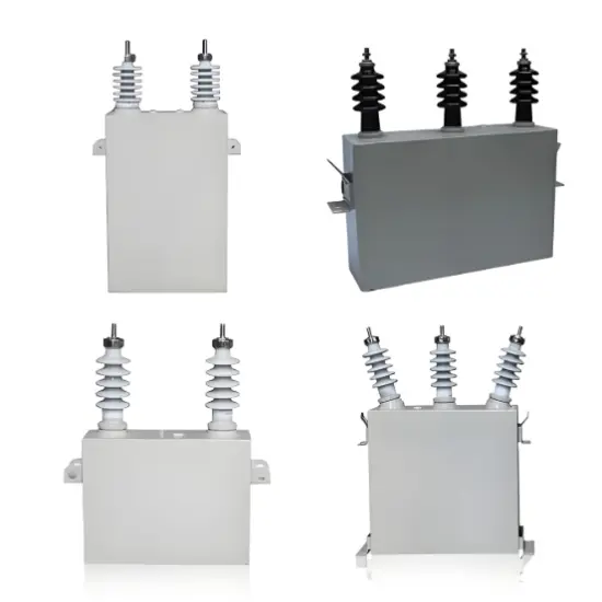
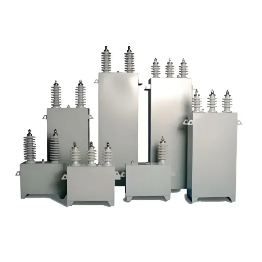
Capacitor cabinet (passive): The lowest cost, graded switching (response 200-500ms), suitable for steady-state loads, requires additional filtering to prevent harmonics, suitable for budget limited small and medium-sized customers and entry-level scenarios in emerging markets, in compliance with IEC 60871.
SVC (Semi Controlled Hybrid): Medium cost, continuous regulation (response 20-40ms), suitable for moderate fluctuating loads, with a small amount of harmonics, suitable for traditional industrial transformation, in compliance with IEC 61921.
SVG (Fully Controlled Active): High cost but excellent performance, fast response (≤ 5ms), high-precision stepless compensation, strong low-voltage ride through capability, suitable for impact/new energy loads, low harmonic, compact design, in line with CE/UL/KEMA, is the preferred choice for high-end markets and new energy projects.
Selection core: Choose capacitor cabinet for steady-state load, SVC for moderate fluctuation, SVG for dynamic/high-end demand, all of which need to match international standards such as IEC.