What Is Common Grounding?Common grounding refers to the practice where a system’s functional (working) grounding, equipment protective grounding, and lightning protection grounding share a single grounding electrode system. Alternatively, it may mean that grounding conductors from multiple electrical devices are connected together and linked to one or more common grounding electrodes.1. Advantages of Common Grounding Simpler system with fewer grounding conductors, making maintenance and inspecti
11/05/2025
Consult
Tip
(1) Generator Protection:Generator protection covers: phase-to-phase short circuits in stator windings, stator ground faults, inter-turn short circuits in stator windings, external short circuits, symmetrical overload, stator overvoltage, single- and double-point grounding in the excitation circuit, and loss of excitation. Tripping actions include shutdown, islanding, limiting fault impact, and alarm signaling.(2) Transformer Protection:Power transformer protection includes: phase-to-phase short
11/05/2025
Consult
Tip

Measure DC resistance: Use a bridge to measure the DC resistance of each high- and low-voltage winding. Check whether the resistance values among phases are balanced and consistent with the manufacturer’s original data. If phase resistance cannot be measured directly, line resistance may be measured instead. The DC resistance values can indicate whether the windings are intact, whether there are short circuits or open circuits, and whether the contact resistance of the tap changer is normal. If
11/04/2025
Consult
Tip
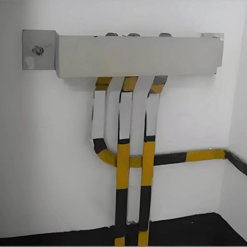
Front-panel visible wiring: During manual wiring (not using templates or molds), wiring must be straight, neat, closely attached to the mounting surface, rationally routed, and with secure connections that facilitate maintenance. Wiring channels should be minimized as much as possible. Within the same channel, bottom-layer conductors shall be grouped by main and control circuits, arranged in a single-layer parallel dense layout or bundled, and kept closely attached to the mounting surface. Condu
11/04/2025
Consult
Tip
The tap changer operating handle shall be equipped with a protective cover. The flange at the handle shall be well sealed with no oil leakage. Locking screws shall securely fasten both the handle and the drive mechanism, and the handle rotation shall be smooth without binding. The position indicator on the handle shall be clear, accurate, and consistent with the tap voltage regulation range of the winding. Limit stops shall be provided at both extreme positions. The insulating cylinder of the t
11/04/2025
Consult
Tip
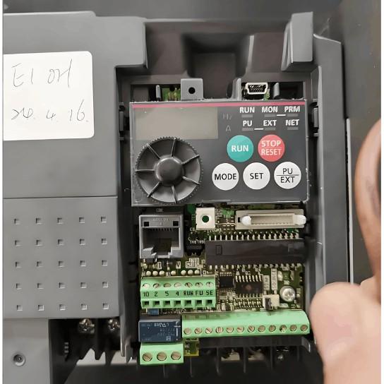
Common inverter faults mainly include overcurrent, short circuit, ground fault, overvoltage, undervoltage, phase loss, overheating, overload, CPU malfunction, and communication errors. Modern inverters are equipped with comprehensive self-diagnostic, protection, and alarm functions. When any of these faults occurs, the inverter will immediately trigger an alarm or shut down automatically for protection, displaying a fault code or fault type. In most cases, the fault cause can be quickly identifi
11/04/2025
Consult
Tip
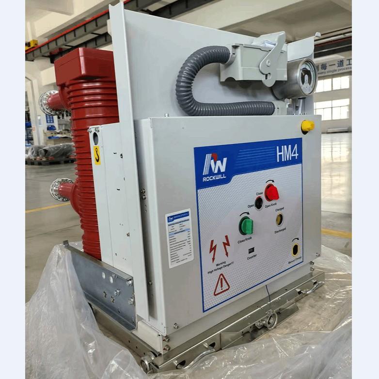
Causes of Dielectric Withstand Failure in Vacuum Circuit Breakers: Surface contamination: The product must be thoroughly cleaned before dielectric withstand testing to remove any dirt or contaminants.Dielectric withstand tests for circuit breakers include both power-frequency withstand voltage and lightning impulse withstand voltage. These tests must be performed separately for phase-to-phase and pole-to-pole (across the vacuum interrupter) configurations.Circuit breakers are recommended to be t
11/04/2025
Consult
Tip

There are many taboos and problematic practices in the installation of distribution boards and cabinets that must be noted. Especially in certain areas, improper operations during installation may lead to serious consequences. For cases where the precautions were not followed, some corrective measures are also provided here to remedy previous mistakes. Let’s follow along and take a look at common installation taboos from manufacturers regarding distribution boxes and cabinets!1. Taboo: Lighting
11/04/2025
Consult
Tip
Overhaul Items for Transformer Conservator:1. Ordinary-Type Conservator Remove the end covers on both sides of the conservator, clean rust and oil deposits from inner and outer surfaces, then apply insulating varnish to the inner wall and paint to the outer wall; Clean components such as the dirt collector, oil level gauge, and oil plug; Check that the connecting pipe between the explosion-proof device and the conservator is unobstructed; Replace all sealing gaskets to ensure good sealing with n
11/04/2025
Consult
Tip
Based on years of field statistics on switchgear accidents, combined with analysis focusing on the circuit breaker itself, the main causes have been identified as: failure of operation mechanism; insulation faults; poor breaking and closing performance; and poor conductivity.1.Failure of Operation MechanismFailure of operation mechanism manifests as delayed operation or unintended operation. Since the most basic and important function of a high-voltage circuit breaker is to operate correctly and
11/04/2025
Consult
Tip


