What Is Common Grounding?
Common grounding refers to the practice where a system’s functional (working) grounding, equipment protective grounding, and lightning protection grounding share a single grounding electrode system. Alternatively, it may mean that grounding conductors from multiple electrical devices are connected together and linked to one or more common grounding electrodes.
Simpler system with fewer grounding conductors, making maintenance and inspection easier.
The equivalent grounding resistance of multiple grounding electrodes connected in parallel is lower than the total resistance of separate, independent grounding systems. When the building’s structural steel or rebar is used as the common grounding electrode—due to its inherently low resistance—the benefits of common grounding become even more pronounced.
Enhanced reliability: if one grounding electrode fails, others can compensate.
Reduced number of grounding electrodes, lowering installation and material costs.
In the event of an insulation failure causing a phase-to-chassis short circuit, a larger fault current flows, ensuring protective devices operate quickly. This also reduces touch voltage when personnel contact faulty equipment.
Mitigates hazards from lightning overvoltages.
Theoretically, to prevent lightning-induced back-flashover, lightning protection grounding should be kept at a safe distance from building structures, electrical equipment, and their grounding systems. However, in real-world engineering, this is often impractical. Buildings typically have numerous incoming utility lines (power, data, water, etc.) spread over wide areas. Especially when reinforced concrete structural rebars are used as concealed lightning protection conductors, it becomes virtually impossible to electrically isolate the lightning protection system from building piping, equipment enclosures, or power system grounding.
In such cases, common grounding is recommended—connecting the transformer neutral, all functional and protective grounds of electrical equipment, and the lightning protection system to the same grounding electrode network. For example, in high-rise buildings, integrating electrical grounding with the lightning protection system effectively forms a Faraday cage using the building’s internal steel framework. All internal electrical equipment and conductors bonded to this cage are thereby protected from lightning-induced potential differences and back-flashover.
Therefore, when utilizing a building’s metallic structure for grounding, common grounding for multiple systems is not only feasible but advantageous, provided the overall grounding resistance is maintained below 1 Ω.
Nature of grounding currents:
The risk associated with ground potential rise (GPR) depends on the magnitude, duration, and frequency of grounding currents. For instance, lightning arresters or rods may carry very high currents during a strike, but these events are brief and infrequent—so the resulting GPR poses limited risk.
However, the common grounding resistance must satisfy the most stringent requirement among all connected systems, ideally ≤1 Ω.
In low-voltage distribution systems with solidly grounded neutrals, the common grounding electrode may carry continuous leakage currents from all connected loads, forming circulating ground currents. If the grounding resistance drifts above safe limits, it can endanger both equipment and personnel.
Moreover, with the widespread use of computers and sensitive electronic equipment, filter grounding is often required. Large line-to-ground EMI/RFI filters introduce significant capacitive leakage currents to earth, which also contribute to the total ground current.
Impact of ground potential rise on connected equipment:
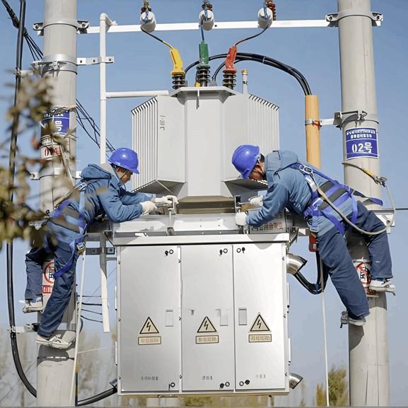
Consider an indoor compact substation unit as an example. Traditionally, the transformer neutral, metal enclosure, and load equipment chassis were all connected to a common ground. Meanwhile, lightning arresters were often given a separate ground to avoid dangerous potential rise during discharge.
However, if a load device develops an insulation fault and leaks current, the entire fault loop current flows through the common grounding electrode, raising the local ground potential—and consequently, the enclosure voltage of the switchgear. If maintenance personnel open the cabinet door under these conditions, they risk electric shock. Such incidents have occurred repeatedly.
As a result, modern practice often isolates functional grounding (e.g., transformer neutral) from protective and lightning grounding in indoor substations—even though this increases installation complexity.
According to current Chinese power industry standards:
For Class B electrical installations, if the supplying distribution transformer is not located within a building containing Class B equipment, and its high-voltage side operates in an ungrounded, Petersen coil (arc-suppression coil)-grounded, or high-resistance grounded system, then the low-voltage system’s working ground may share the same grounding electrode as the transformer’s protective ground, provided the grounding resistance satisfies R ≤ 50/I (Ω) and R ≤ 4 Ω.
For Class A electrical installations operating in effectively grounded systems, the transformer’s working ground must be located outside the protective grounding grid—i.e., common grounding is not permitted.
If the distribution transformer is installed inside a building with Class B electrical installations, and its high-voltage side uses low-resistance grounding, then the low-voltage working ground may share the protective ground if:
Grounding resistance meets R ≤ 2000/I (Ω), and
The building implements a main equipotential bonding (MEB) system.
Additionally, for systems above 1 kV classified as large grounding short-circuit current systems, common grounding is permissible if rapid fault clearance is ensured, but the grounding resistance must be < 1 Ω.
Protective grounding of distribution transformers in Class A installations may share the same grounding electrode as the associated lightning arrester grounding.
Practical experience shows that in public low-voltage distribution systems, where complete separation of grounding systems is often unachievable, common grounding—combining working, protective, and lightning grounding—is safer, more economical, simpler to install, and easier to maintain.
To mitigate potential risks of common grounding, engineers should:
Fully utilize the building’s structural steel as a natural grounding electrode,
Maintain total grounding resistance below 1 Ω, and
Implement comprehensive equipotential bonding throughout the facility.
These measures effectively minimize hazards and ensure safe, reliable operation of modern electrical installations.