I. Analysis of the Principle of Power System Voltage Regulators
Before analyzing the principle of power system voltage regulators, it is necessary to analyze the excitation regulator and draw conclusions through comparison. In practical application, the excitation regulator uses voltage deviation as a feedback quantity for adjustment, thereby keeping the generator terminal voltage within the standard range. However, this type of voltage regulator, especially during grid faults, requires a large amount of reactive power to improve grid voltage stability and ensure power system quality. Since the main goal of the excitation regulator is to control the generator terminal voltage, it is difficult to ensure grid voltage stability.
In this case, the voltage regulator should be improved. Relevant studies show that by introducing the system voltage, the main transformer of the generator and the excitation regulator will jointly control the generator terminal, and the generator step-up transformer will be controlled based on the compensation method while increasing the generator's reactive power, thus improving the stability of the power system. The principle of the power system voltage regulator is to control the generator by introducing the corresponding voltage together with the excitation voltage. When the speed of the AC generator increases, the power system voltage regulator will reduce the excitation current and magnetic flux to stabilize the voltage, thereby ensuring the safe and stable operation of the power grid.
In practical application, the voltage system voltage regulator consists of components such as the high-voltage bus, generator terminal voltage setpoint, amplification factor, phase compensation, output limiting, and on/off control. The moment the power system voltage regulator is turned on or off has little impact on the regulator and generator power. Under equivalent conditions, the power system voltage regulator can reduce the main transformer's resistance and reactance to a certain extent during operation; the reduction degree varies with the ratio of the generator terminal voltage setpoint, but overall, it has little impact on the droop coefficient and power droop coefficient.
However, to prevent reactive power competition when the voltage regulator of a two-generator power system is actively shut down, the terminal parallel generators need to be set based on the corrected droop rate, while also paying attention to the main transformer's reactance and resistance. When the main transformer's reactance and resistance of the power system voltage regulator decrease, the terminal main transformer's reactance and resistance are usually zero. If the unit operates based on the droop rate, efforts should be made to increase the power system's stability value and the excitation system's support for grid voltage. However, ensuring power system stability in this way still poses certain challenges.
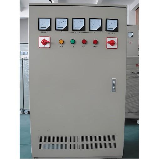
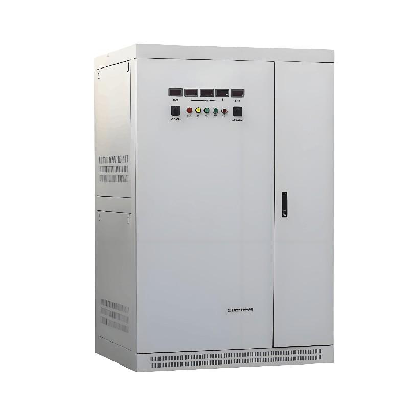
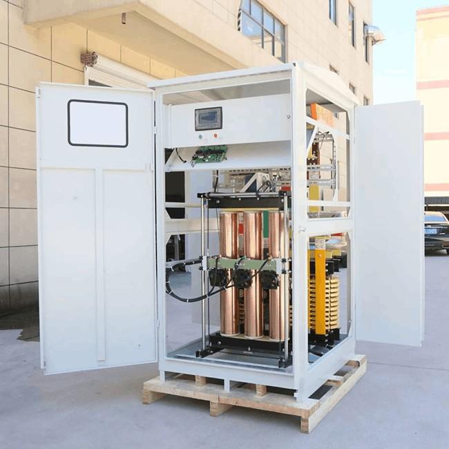
.jpg")
II. Analysis of Power System Voltage Regulator Experiments
In the actual operation of the power system voltage regulator, especially when a single unit is connected to an infinite bus system via a double-circuit line, short circuits are likely to occur in the circuit. Once a short circuit occurs, the terminal voltage and electromagnetic power will decrease. Coupled with the unadjusted prime mover power, the rotor tends to accelerate, and reactive power may even be depleted, thus undermining the voltage stability of the power system.
Traditional excitation systems cannot control voltage effectively. In contrast, the high-voltage side control of the terminal voltage, due to the close connection between the high-voltage bus and the system, tends to cause a rapid voltage drop at the initial stage of a fault, making its response more sensitive. After a short-circuit fault, the generator terminal voltage and the main transformer's high-side voltage rise faster than with the excitation regulator, stabilizing the voltage in a short time and thus ensuring the stability of the voltage bus.
To enable the power system voltage regulator to function better, its system should be calculated accordingly. During the calculation, the impact of the excitation control mode on the critical clearing time is analyzed based on simple systems and actual systems. When calculating the single-machine infinite bus system, the infinite bus structure, generator dynamic model, transformer impedance, and the impedance of the two-circuit transformer power system voltage regulator (Principles and Experimental Analysis, Zheng Changquan, Guangzhou Baiyun Electric Equipment Co., Ltd.) should be clarified. On this basis, the power system short circuit is analyzed, and the corresponding results are obtained through simulation calculations. The results show that the excitation regulator and power system voltage regulator have little correlation with the critical clearing time.
When calculating the actual system, the grid structure of a certain power grid company can be used as the calculation network, and the operating generator of a certain power plant is analyzed accordingly. On this basis, the power system short-circuit fault is analyzed. The results show that when the critical clearing time is at the standard value, the power system voltage regulator does not respond effectively under the fault.
To better analyze the power system voltage regulator, connect the single unit directly to the grid system via a single line, close the high-side switch of the generator main transformer (ensure the line switch is open), select different amplification factors based on this configuration, and analyze the excitation control system using the generator no-load voltage step response simulation calculation method. The results show that if the amplification factor is too large, the power system will experience no-load stability issues. To better solve this problem, it is advisable to use the high-voltage bus control function method during the no-load test.
The power system voltage regulator can also be analyzed under the same bus. In the experimental analysis, emphasis should be placed on solving the reactive power distribution problem between parallel generators. In practice, the same power system voltage should be adjusted to achieve the same positive droop. In the actual operation of a power plant, simulation calculations were used to combine the original excitation regulator with the power system voltage regulator, and they jointly addressed the reactive power deficit of the power system. The results show that there was no power competition during unit operation, and the reactive power distribution was relatively reasonable.
III. Conclusion
With the continuous development of information technology, dynamic power quality issues have become a focus for the safe and orderly operation of power grids. Relying solely on the original excitation regulator cannot achieve the goal of safe and orderly grid operation. In this case, compensation devices are needed to solve voltage problems. The combination of the power system voltage regulator and the excitation regulator meets practical needs to a certain extent. However, to better apply the power system voltage regulator in the power grid, its principle and test results need to be analyzed.
As the times progress, new problems will emerge in the power grid. To better solve these problems, further analysis of the principle of the power system voltage regulator is required.