Bixîna diharên bêyirhastanîn ji bo kontrola hêzînên motoran AC û serpilindar ne ku li ser çendî pargiran yên wekî digerîn, metelûjî, nîfet, û têkîşîn bûyer bikin. Lekin, di dema xebitandina wan de, bixînan diharên bêyirhastanîn 6kV derbasên anormalkirinê ya drîvî dibe navbera astengkirina şêtana rêjan û têkiliya barkirinê, ku hêzîn û agahdarîya sistemên kontrola hêzînê ya motoran biguherîne.
Bi tenê li vir bikekirina werzekariya şêtana vêrên bi haranîn, hilînêweriya industrî û kamkirina energeyê, hukûmet parêzeyên yekparast kiribûn ku aliyarî û bikaranîna teknolojîya bixîna diharên bêyirhastanîn bide. Naverok, analîzêya derbarê derbasên anormalkirinê ya bixîna diharên bêyirhastanîn 6kV û çêkerina xasa pêşniyar ên dikare berhemî be li ser piştguhîna teknolojîya VFD bêyirhastanîn û dayîna ekonomîyê industrî.
1 Têkilîna Bixîna Diharên Bêyirhastanîn 6kV
Bixîna diharên bêyirhastanîn 6kV û bêdihêr ûst pirgirîya elektronîkî ya guhertoya IGBT-yan wan bibînin diharên bêyirhastanîn bi tevahîna multilevel in, ku hêzîn û agahdarîya kontrola hêzînê li vir 6kV ve girîde. Birîyan û herîyan wê heke karîbîn 3L-NPC an 5L-ANPC dibînin, ku ji bo lêgerîna submodulan reyandin. Her submodule 6-24 IGBT û diodên freewheeling din dibînin, ku wara grafikên sathî hatine 9-17 lewel, ku pasîn îroçîna grafikê sînusî dibe.
Dema kapasîtekî yên bexwesta 3000-14,000 kVA û diharên bêyirhastanîn 6kV, 10kV, û 35kV. Ji bo demên kapasîtekî û diharê bêdihêr, topolojîya converter multilevel modular (MMC) bikar bînin, ku submodulan bikar bînin half-bridge an full-bridge, ku li ser her phase hundranan submodul reyandin, ku hêza bêdihêr derbasên 220kV û kapasîtekî yên bexwesta 400 MVA bibînin, ku li ser çendî barkirinan wekî integrasyon gridi enerjiyê nû, têkîşîna rûbar, û transmisyon DC pêşve birkar bînin. Strategiya kontrolê ya bixîna diharên bêyirhastanîn komplike ye, ku teknolojîên keyman yên wekî modulasyona carrier phase-shifted, balanskirina cûren, deteksiyon sensorless, û optimizasyona field-weakening dibînin.
2 Derbasên Anormalkirinê ya Drîvî ya Bixîna Diharên Bêyirhastanîn 6kV
Di dema xebitandina bixîna diharên bêyirhastanîn 6kV de, derbasên anormalkirinê wek overcurrent, overvoltage, û overheating serpilindar ne. Derbasên overcurrent serpilindar ne navbera destpêkirdinê an guhertoyên barkirinê serpilindar, ku cûreya serpilindar divê biçûkînê 2-3 her çendî nîrvan. Eger cûreya serpilindar 1600A ji 100ms an 2000A ji 10ms da, bixîna IGBT-yan blok bike û kontaktorê bêdihêr veguheze, ku derbasên hardware protection tripping têkildar bike.
Derbasên overvoltage serpilindar ne navbera fluktuasyonên şêtana an guhertoyên barkirinê serpilindar. Eger voltageya bus DC 1.2 her çendî nîrvan (1368V) biguhere, software overvoltage protection active bike; eger 1.35 her çendî nîrvan (1026V) biguhere, hardware protection derbas bike. Derbasên overheating serpilindar ne navbera mîhanên garm û xebitandina barkirinê serpilindar. Eger temperatureya IGBT 90°C an heatsink 70°C ji 5 menit biguhere, sistem warninga garm bike; eger temperatureya 100°C an 80°C biguhere, derbas bike. Xesa derbasên sêta vê ûst aktivkirina mekanîzmeya self-protection ya bixîna, ku output rapidan veguheze bi blok bike IGBT-yan û Kontaktoran, ku fenomenên serpilindar ne wekî darûstkirina emergency stop û warninga derbas flash bike.
3 Xasa Pêşniyar
3.1 Resistor Current-Limiting
Ji bo çareserkirina derbasên overcurrent, resistor current-limiting bi seriyan reyandin di nav bixîna û motor de. Peymana zemînî şoşînin ku meta bixîna 6kV/1500kVA destpêkirî motor 380kW an bêdihêr bibe, cûreya destpêkirdinê serpilindar divê 5-8 her çendî nîrvan biguhere, ku çend her çendî nîrvan biguhere overcurrent protection setting.
Ji bo supresiyon cûreya destpêkirdinê, resistor wire-wound an varistor zinc-oxide nonlinear bi resistance 1-3Ω û power rated 200-500W bikar bînin. Yekemîn cold-state resistance above 100Ω û bi serpilindara cûreya serpilindar rapidan biguhere, ku peak starting current within 2-3 her çendî nîrvan biguhere. Pas destpêkirdinê motor, meta frequency bixîna bêdihêr above 40Hz û cûreya below the rated value, drop voltage across the resistor less than 50V.
Li vir, bypass contactor resistor short bike to avoid continuous power loss. Eger cûreya serpilindar bi destpêkirdinê, meta current transformer detects value exceeding 1200A, control system warning bike; eger 1500A biguhere, bixîna immediately blocks IGBT-yan û opens bypass contactor, resistor current-limiting reinserts to rapidly reduce current. Bypass contactor then reclosed to restore normal operation. The entire switching process takes less than 0.5s, effectively suppressing current spikes, ensuring smooth motor startup, and significantly enhancing inverter reliability.
3.2 Voltage Clamping Circuit
Ji bo çareserkirina derbasên overvoltage, circuit voltage clamping bi parallel reyandin di bus DC de. Ev circuit mainly consists of a metal oxide varistor (MOV), a fast thyristor (GTO), and a detection circuit. Peymana zemînî şoşînin ku software overvoltage protection activates when grid voltage fluctuates more than 15% or when load reduction causes the DC bus voltage to exceed 1300V for over 20ms.
Ji bo prevent such faults, a TYN-20/141 MOV can be used, with a triggering voltage of 1420V, maximum discharge current of 20kA, and energy absorption capacity of 8800J per unit. When the bus voltage exceeds 1350V, the MOV begins to conduct and absorb excess energy; if the voltage rises to 1400V, the GTO triggers, rapidly diverting the overvoltage energy into a resistor to restore voltage to a safe level. The detection circuit continuously monitors the bus voltage.
When the voltage drops below 1250V and remains there for 50ms, a release signal is sent, turning off the GTO and restoring normal system operation. If the bus voltage remains above 1400V for more than 100ms, a severe overvoltage fault is identified, and the inverter enters a software lockout state, requiring manual reset before restart. Practice shows that with this clamping circuit, a 6kV inverter can withstand 35% instantaneous overvoltage and suppress overvoltage to within 1.05 times the rated voltage within 100ms. The response is fast and reliable, effectively preventing frequent overvoltage tripping and significantly improving system continuity and reliability.
3.3 Current-Sharing Design
Ji bo çareserkirina derbasên overheating, teknolojîya current-sharing bikar bînin ji bo redkirina heat generation û herîyan keyman yên wekî IGBT-yan û heatsinks, ku prevent thermal tripping.
Xasa specific include connecting 1-2 electrolytic capacitors in parallel across the positive and negative DC bus terminals of each power unit. Capacitors should have a capacitance of 1000-2200μF, voltage rating ≥1600V, and continuous ripple current ≥100A. When the inverter output current exceeds 1.2 times the rated value (e.g., 900A), these parallel capacitors can provide 10%-20% current sharing capability, reducing the actual current through the IGBTs to 720-810A. Given that IGBT conduction losses are proportional to the square of the current, this approach effectively reduces temperature rise.

In the formula: PC is the IGBT conduction loss (W); VCE is the IGBT saturation voltage (V), which has a linear relationship with the current IC (A); Uη is the turn-on voltage of the IGBT (V); K is the current amplification factor of the IGBT.
It can be seen that after taking shunt measures, the conduction loss of the IGBT can be reduced by 19% to 36%, and the chip junction temperature can decrease by 10°C to 25°C, thus greatly alleviating the heating problem of the inverter.
In addition, install 1 to 2 electric fans in parallel at the inlet and outlet of the inverter heat sink, with a rated air volume of ≥ 3000 m³/h, which can effectively enhance the cooling effect of the heat sink. Set up 6 to 8 temperature sensors inside the control cabinet to monitor the temperatures of various power units, Mother board, IGBT drive board, etc., in real time. When any point's temperature exceeds 65°C, the control system immediately starts the electric fan at full speed and sends a "load reduction warning" signal to the inverter control unit.
If the temperature continues to rise to 75°C and lasts for more than 10 minutes, the system issues an "over-temperature alarm" signal, limiting the maximum output current of the inverter to below 50% of the rated value until the temperature drops below 60°C, at which point the "over-temperature alarm" is lifted.
If any measurement point's temperature exceeds 85°C and the motor current does not drop below 30% of the rated value, the inverter immediately locks out hardware and stops output. To further improve the cooling effect, apply nanomaterials such as graphene or carbon nanotubes on the IGBT heat sinks of each power unit, utilizing their ultra-high thermal conductivity to accelerate the heat dissipation of the IGBT chips, thereby reducing the junction temperature.
4 Effectiveness of Preventive Measures
4.1 Experimental Design
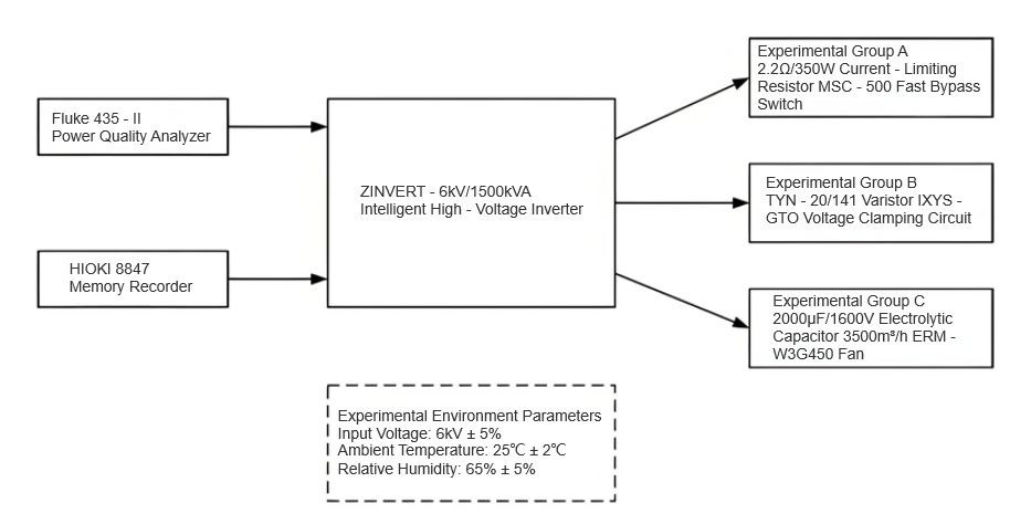
The ZINVERT-6kV/1500kVA intelligent high-voltage inverter was used as the test object, and a grouped control experiment was conducted to verify the effectiveness of the three proposed preventive measures. The experiments were carried out under rated operating conditions (input voltage: 6kV±5%; ambient temperature: 25°C±2°C; relative humidity: 65%±5%). The experiment was divided into four groups: the control group adopted no preventive measures; Group A employed a 2.2Ω/350W current-limiting resistor with an MSC-500 fast bypass switch; Group B used a voltage clamping circuit formed by a TYN-20/141 varistor and an IXYS-GTO connected in parallel, with the clamping voltage set at 1420V; Group C utilized a 2000μF/1600V electrolytic capacitor (Hitachi HCG series) connected in parallel for current sharing, combined with a 3500 m³/h variable-speed fan (EBM-W3G450) for forced cooling.
Each group operated continuously for 72 hours, with key parameters—such as inverter output current, DC bus voltage, and IGBT junction temperature—recorded every 6 hours. Data were collected using a Fluke 435-II power quality analyzer and an HIOKI 8847 data logger. During the experiment, three typical fault scenarios were simulated: inrush overcurrent (8 times rated current / 0.5s), grid voltage fluctuation (+20% / 1s), and full-load operation (ambient temperature 35°C / 2h). The experimental setup is shown in Figure 1.
4.2 Result Analysis
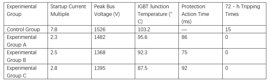
After 72 hours of continuous operation, data from the four groups were collected and analyzed, with results presented in Table 1. The control group experienced tripping under all three fault conditions, whereas the experimental groups with preventive measures demonstrated effective fault suppression. In Group A, the peak starting current was reduced from 7.8 to 2.2 times the rated value, effectively preventing overcurrent tripping.
In Group B, the voltage clamping circuit limited the maximum DC bus voltage fluctuation to 1368V, well below the 1420V protection threshold. In Group C, the combination of current sharing and forced cooling maintained the maximum IGBT junction temperature below 87.5°C, significantly lower than the 100°C tripping threshold. Furthermore, the response time of all three preventive measures was within 100ms, meeting the requirement for fast protection. No false triggering occurred during the experiment, indicating stable and reliable system performance.
5 Conclusion
This study systematically analyzed the causes of abnormal tripping in 6kV high-voltage inverters and proposed targeted preventive measures. Experimental results confirm that the current-limiting resistor effectively controls inrush current, the voltage clamping circuit significantly suppresses DC bus overvoltage, and the combination of current sharing with forced cooling greatly reduces the risk of IGBT overheating, thereby enhancing the overall reliability of the system.