Augstsprieguma invertori ir kritiski svarīgi ierīces ātruma regulēšanai AC motoros un tiek plaši izmantoti augstas jaudas, augstsprieguma motoru ātruma regulēšanai tādās nozarēs kā paceltāji, metallurgija, nafta un enerģijas ražošana. Tomēr, darbības laikā 6kV augstsprieguma invertori bieži saskaras ar nevalīgu pārtraukumu defektu dēļ faktoru, piemēram, tīkla svārstību un slodzes ietekmes, kas būtiski ietekmē motoru ātruma regulēšanas sistēmas drošību un uzticamību.
Lai nodrošinātu augstsprieguma mainīgā frekvences pogu (VFD) sistēmu stabilitāti, uzlabotu rūpniecisko efektivitāti un samazinātu enerģijas patēriņu, valdība ir ieviesusi virkni politikas pasākumu, kas veicina augstsprieguma inverteru tehnoloģiju pētījumus un pielietojumu. Tādēļ, 6kV augstsprieguma inverteru nevalīgu pārtraukumu defektu cēloku ganiem analīze un efektīvu novēršanas pasākumu izstrāde ir ļoti nozīmīga augstsprieguma VFD tehnoloģijas progresēšanai un rūpnieciskās ekonomikas ilgtspējīgai izaugsmei.
1 6kV Augstsprieguma Inverteru Pārskats
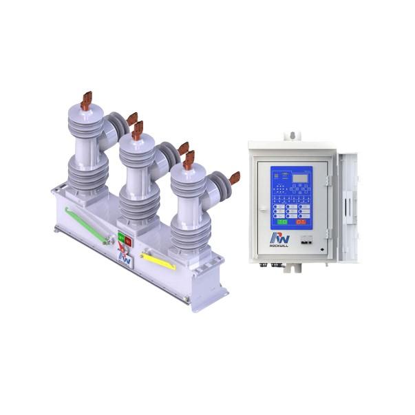
6kV augstsprieguma invertis ir augstas jaudas elektroniskā ierīce, kas izmanto IGBT kā pārslēgējus un izmanto daudzlīmeņu topoloģiju, lai sasniegtu mainīgo frekvences ātruma regulēšanu 6kV un augstāk. Tās jaudas vienības parasti izmanto trīs līmeņu neutrales punkta fiksēto (3L-NPC) vai piecus līmeņu aktīvo neutrales punkta fiksēto (5L-ANPC) shēmas, kas ir konstruētas, savienojot vairākas submoduļus. Katrs submodulis satur 6–24 IGBT un brīvās diodas, radot soļveida formu ar 9–17 līmeņiem, kas pēc filtrēšanas tuvinās sinusoīdai.
Parastā jauda atrodas no 3000 līdz 14 000 kVA, ar sprieguma līmeņiem, kas ietver 6kV, 10kV un 35kV. Lai apmierinātu augstākas jaudas un sprieguma prasības, var izmantot modulāru daudzlīmeņu konverteru (MMC) topoloģiju, kur submoduļi izmanto puspuķes vai pilnīgas puķes struktūras, ar simtiem submoduļu katrā fāzē, ļaujot sasniegt līdz 220kV un vienības jaudu līdz 400 MVA, piemērotu lietojumam, piemēram, atjaunojamās enerģijas tīklu integrācijai, jūras piekrastes vēja enerģijai un elastīgai DC transmisijai. Augstsprieguma inverteru vadības stratēģija ir sarežģīta, iesaistot galvenās tehnoloģijas, piemēram, nosūtītāju fāzes maiņa, strāvas balansēšana, bezsensora detektājs un lauka sajaukšanas optimizācija.
2 6kV Augstsprieguma Inverteru Nevalīgie Pārtraukumu Defekti
Darbības laikā 6kV augstsprieguma invertori bieži pārtrauc operācijas dēļ pārstrāvas, pārsprieguma un pārsildīšanās defektu. Pārstrāvas defekti parasti notiek startēšanas laikā vai neparedzētās slodzes maiņas laikā, kad momentānā strāva var pārsniekt 2–3 reizes nomālā vērtība. Ja strāva pārsniedz 1600A vairāk kā 100ms vai 2000A vairāk kā 10ms, invertis tūlītēji bloķē IGBT un atseko izvades kontaktoru, aktivizējot hardware aizsardzības pārtraukumu.
Pārsprieguma defekti parasti rodas dēļ tīkla svārstībām vai neparedzētās slodzes maiņas. Kad GSP līnijas spriegums pārsniedz 1.2 reizes nomālā vērtība (1368V), aktivizējas programmatūras pārsprieguma aizsardzība; ja tas pārsniedz 1.35 reizes (1026V), hardware aizsardzība tūlītēji pārtrauc. Pārsildīšanās defekti parasti notiek augstā temperatūrā vai ilgstošā pārmērīgā operācijā. Kad IGBT temperatūra pārsniedz 90°C vai ledentāka temperatūra pārsniedz 70°C vairāk kā 5 minūtes, sistēma izsūna augstas temperatūras brīdinājumu; pārtraukums notiek tūlītēji, ja temperatūras sasniedz 100°C vai 80°C attiecīgi. Šo trim defektu tipiem ir kopīga īpašība — invertis paša aizsardzības mehānisma aktivizācija, kas ātri atseko izvadi, bloķējot IGBT un atsekojot kontaktorus, rezultējot fenomeniem, piemēram, motora ārkārtas stopa un mitinājoši blakusā defekta signāli.
3 Novēršanas Pasākumi
3.1 Strāvas Ierobežojoša Rezistora
Lai risinātu pārstrāvas defektus, starp invertera izvadi un motoru var savienot strāvas ierobežojošu rezistoru. Teritorijas mērījumi liecina, ka, kad 6kV/1500kVA invertis startē 380 kW vai lielāku motoru, momentānais startēšanas strāvas picis var sasniedzt 5–8 reizes nomālā strāva, pārsniedzot pārstrāvas aizsardzības iestatījumu.
Lai samazinātu startēšanas strāvu, var izmantot drātas apvijumu rezistoru vai nelīniju zinc oksīda varistoru ar rezistīvību 1–3Ω un nominālo jaudu 200–500W. Otrs ir ar kaltas stāvokļa rezistīvību virs 100Ω un strāvas pieauguma dēļ strauji samazinās, ierobežojot maksimālo startēšanas strāvas picu līdz 2–3 reizes nomālajai vērtībai. Motoru startējot, kad invertera izvades frekvence pārsniedz 40Hz un strāva krit below the rated value, the voltage drop across the resistor is less than 50V.
At this point, a bypass contactor shorts the resistor to avoid continuous power loss. If current surges during startup, when the current transformer detects a value exceeding 1200A, the control system issues a warning; if it reaches 1500A, the inverter immediately blocks the IGBTs and opens the bypass contactor, reinserting the current-limiting resistor to rapidly reduce current. The bypass contactor is then reclosed to restore normal operation. The entire switching process takes less than 0.5s, effectively suppressing current spikes, ensuring smooth motor startup, and significantly enhancing inverter reliability.
3.2 Voltage Clamping Circuit
To suppress overvoltage faults, a voltage clamping circuit can be connected in parallel to the DC bus. This circuit mainly consists of a metal oxide varistor (MOV), a fast thyristor (GTO), and a detection circuit. Field data show that software overvoltage protection activates when grid voltage fluctuates more than 15% or when load reduction causes the DC bus voltage to exceed 1300V for over 20ms.
To prevent such faults, a TYN-20/141 MOV can be used, with a triggering voltage of 1420V, maximum discharge current of 20kA, and energy absorption capacity of 8800J per unit. When the bus voltage exceeds 1350V, the MOV begins to conduct and absorb excess energy; if the voltage rises to 1400V, the GTO triggers, rapidly diverting the overvoltage energy into a resistor to restore voltage to a safe level. The detection circuit continuously monitors the bus voltage.
When the voltage drops below 1250V and remains there for 50ms, a release signal is sent, turning off the GTO and restoring normal system operation. If the bus voltage remains above 1400V for more than 100ms, a severe overvoltage fault is identified, and the inverter enters a software lockout state, requiring manual reset before restart. Practice shows that with this clamping circuit, a 6kV inverter can withstand 35% instantaneous overvoltage and suppress overvoltage to within 1.05 times the rated voltage within 100ms. The response is fast and reliable, effectively preventing frequent overvoltage tripping and significantly improving system continuity and reliability.
3.3 Current-Sharing Design
To address overheating faults, current-sharing technology can be used to reduce heat generation in critical components such as IGBTs and heatsinks, preventing thermal tripping.
Specific measures include connecting 1–2 electrolytic capacitors in parallel across the positive and negative DC bus terminals of each power unit. The capacitors should have a capacitance of 1000–2200μF, voltage rating ≥1600V, and continuous ripple current ≥100A. When the inverter output current exceeds 1.2 times the rated value (e.g., 900A), these parallel capacitors can provide 10%–20% current sharing capability, reducing the actual current through the IGBTs to 720–810A. Given that IGBT conduction losses are proportional to the square of the current, this approach effectively reduces temperature rise.

In the formula: PC is the IGBT conduction loss (W); VCE is the IGBT saturation voltage (V), which has a linear relationship with the current IC (A); Uη is the turn-on voltage of the IGBT (V); K is the current amplification factor of the IGBT.
It can be seen that after taking shunt measures, the conduction loss of the IGBT can be reduced by 19% to 36%, and the chip junction temperature can decrease by 10°C to 25°C, thus greatly alleviating the heating problem of the inverter.
In addition, install 1 to 2 electric fans in parallel at the inlet and outlet of the inverter heat sink, with a rated air volume of ≥ 3000 m³/h, which can effectively enhance the cooling effect of the heat sink. Set up 6 to 8 temperature sensors inside the control cabinet to monitor the temperatures of various power units, Mother board, IGBT drive board, etc., in real time. When any point's temperature exceeds 65°C, the control system immediately starts the electric fan at full speed and sends a "load reduction warning" signal to the inverter control unit.
If the temperature continues to rise to 75°C and lasts for more than 10 minutes, the system issues an "over-temperature alarm" signal, limiting the maximum output current of the inverter to below 50% of the rated value until the temperature drops below 60°C, at which point the "over-temperature alarm" is lifted.
If any measurement point's temperature exceeds 85°C and the motor current does not drop below 30% of the rated value, the inverter immediately locks out hardware and stops output. To further improve the cooling effect, apply nanomaterials such as graphene or carbon nanotubes on the IGBT heat sinks of each power unit, utilizing their ultra-high thermal conductivity to accelerate the heat dissipation of the IGBT chips, thereby reducing the junction temperature.
4 Effectiveness of Preventive Measures
4.1 Experimental Design
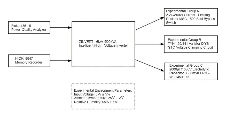
The ZINVERT-6kV/1500kVA intelligent high-voltage inverter was used as the test object, and a grouped control experiment was conducted to verify the effectiveness of the three proposed preventive measures. The experiments were carried out under rated operating conditions (input voltage: 6kV±5%; ambient temperature: 25°C±2°C; relative humidity: 65%±5%). The experiment was divided into four groups: the control group adopted no preventive measures; Group A employed a 2.2Ω/350W current-limiting resistor with an MSC-500 fast bypass switch; Group B used a voltage clamping circuit formed by a TYN-20/141 varistor and an IXYS-GTO connected in parallel, with the clamping voltage set at 1420V; Group C utilized a 2000μF/1600V electrolytic capacitor (Hitachi HCG series) connected in parallel for current sharing, combined with a 3500 m³/h variable-speed fan (EBM-W3G450) for forced cooling.
Each group operated continuously for 72 hours, with key parameters—such as inverter output current, DC bus voltage, and IGBT junction temperature—recorded every 6 hours. Data were collected using a Fluke 435-II power quality analyzer and an HIOKI 8847 data logger. During the experiment, three typical fault scenarios were simulated: inrush overcurrent (8 times rated current / 0.5s), grid voltage fluctuation (+20% / 1s), and full-load operation (ambient temperature 35°C / 2h). The experimental setup is shown in Figure 1.
4.2 Result Analysis
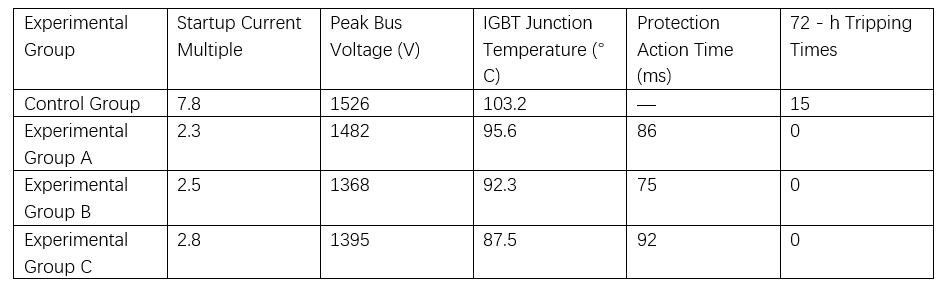
After 72 hours of continuous operation, data from the four groups were collected and analyzed, with results presented in Table 1. The control group experienced tripping under all three fault conditions, whereas the experimental groups with preventive measures demonstrated effective fault suppression. In Group A, the peak starting current was reduced from 7.8 to 2.2 times the rated value, effectively preventing overcurrent tripping.
In Group B, the voltage clamping circuit limited the maximum DC bus voltage fluctuation to 1368V, well below the 1420V protection threshold. In Group C, the combination of current sharing and forced cooling maintained the maximum IGBT junction temperature below 87.5°C, significantly lower than the 100°C tripping threshold. Furthermore, the response time of all three preventive measures was within 100ms, meeting the requirement for fast protection. No false triggering occurred during the experiment, indicating stable and reliable system performance.
5 Conclusion
This study systematically analyzed the causes of abnormal tripping in 6kV high-voltage inverters and proposed targeted preventive measures. Experimental results confirm that the current-limiting resistor effectively controls inrush current, the voltage clamping circuit significantly suppresses DC bus overvoltage, and the combination of current sharing with forced cooling greatly reduces the risk of IGBT overheating, thereby enhancing the overall reliability of the system.