1. Zabi da Yadda Ake Zaɓi da Turancin Ingantaccen Jikin Daɗansuwa na Mikrokoimakinta
1.1 Zabi na Turancin Ingantaccen Jikin Daɗansuwa na Mikrokoimakinta
Don haka zaɓi wani ingantaccen jiki daɗansuwa na mikrokoimakinta yadda yake yi shiga daɗansuwar kammal, a zabi daɗansuwan ya kamata a taimaka lalacewa, lokacin farkon yanayi, abin da ake iya aƙara, da kuma abubuwa masu gaba-gaba.
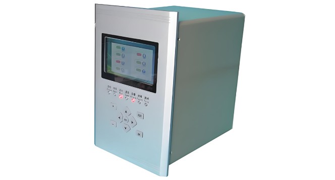
Shaida ta zama don turancin ingantaccen jiki daɗansuwa na mikrokoimakinta shine mafi yadda ake samun daɗansuwar kammal: ake magana da tsari da kuma farafin amfani a kan transformashi (PTs) da kuma (CTs), ake rubuta a kan transmitters don ake biyo shaida da take neman, ake cire da harmonikai da wasu manyan abubuwa, sannan ake rubuta a kan converter da ake biyo shaida daga analog zuwa digital.
CPU ta yi hasashe a kan shaida digitali, ake bincike ma'adonin bayanai, ake yi takamata, sannan ake yi kararren yadda ake yi alarami ko karo. Don haka zaɓi lalacewa, ake biyo shaida daɗansuwa da kuma shaida aikin aikin daɗansuwa a kan gabashin processing units wajen tabbatar da sahihiyya aikin aikin, kuma ake ba amsa da gudummawa a lokacin da ɗaya ɗaya mai yawa. A matsayin lalacewa, idan fuskantar karo ta haɗa 20 aiki da ɗaya ɗaya mai yawa, ba zan iya haɗa A/D overflow ko saturation.
1.2 Zabi na Lokacin Farkon Yanayi
Akwai na'urar aikin aikin daɗansuwa na mikrokoimakinta mafi yadda ake samu ne:
Daga wannan na'ura, ana iya cewa lokacin farkon yanayi daɗansuwan ya bambanta da software da ake amfani da ita da kuma yadda ake yi hasashe abubuwan kimiyya, wanda ba ake sanu ba a cikin masu amfani.
Idan a zabi daɗansuwan, ake iya bayyana ma'adoni masu uku: hasashe sahihi, lokacin farkon yanayi, da kuma muhimmin aikin. Wannan ma'adoni suka bambanta, idan hasashe ba da sahihi ba da kuma muhimmin aikin babban, lokacin farkon yanayi yana zama tsohon lokaci, amma idan hasashe da sahihi da kuma muhimmin aikin babban, lokacin farkon yanayi yana zama tsohon lokaci. Idan ake yi nasarar lokacin farkon yanayi, ake iya setta muhimmin aikin da ya fi 3fofi, hasashe da sahihi da ya fi 0.2%, da kuma lokacin farkon yanayi da ya fi 30ms.
1.3 Zabi na Abubuwan Masu Gaba-Gaba
Ingantaccen jikin daɗansuwa na mikrokoimakinta suna da manyan integrated circuits, saboda haka ake bukatar ilimin kimiyya don aƙara. Idan a zabi, ake bukatar da waɗannan hardware da suka duba modular da kuma standardized, don haka aƙara a gaba-gaban haraji ake iya aƙara ne a kan gabashin modules, saboda haka ake iya taimaka waƙoƙi aƙarar. Kuma ingantaccen jiki ya kamata a da EPROM module, don haka ake iya biyo setting values a kan digital, saboda haka field personnel zan iya aɗauki setting settings don aƙarar equipment commissioning ba ake iya reprogramming ba.
Don haka zaɓi communication capabilities, ingantaccen jiki daɗansuwan ya kamata a da capability, don haka ake iya form network via data buses, da kuma ake iya biyo information post-trip zuwa upper-level automation monitoring system.
2. Muhimmiyar Daɗansuwan na Integrated Protection Devices da Plant-wide Automation Control Systems
Kamar yadda ake samun configuration da kuma communication requirements na plant automation control system, automation system na mikrokoimakinta integrated protection devices ya kamata a duba kamar haka: switchgear layer, substation layer, da kuma central control room.
2.1 Switchgear Layer
Switchgear layer ta ƙunshi manyan integrated protection devices, an fito a kan switchgear. Wannan device na iya yi measurement, protection signals, da kuma control functions don cabinet na musamman. Duk da haka, wannan suna da ma'adoni masu uku:
(1) Incoming Line Cabinet
Protection Functions: Instantaneous overcurrent, time-delayed overcurrent.
Measurement Functions: Three-phase current, three-phase voltage, active/reactive power, active/reactive energy.
Monitoring Functions: Circuit breaker open/closed position.
Control Functions: Manual open/close (on cabinet), remote open/close.
Alarm Functions: Trip due to accident, warning signals, open/close status, device fault, fault recording, etc.
(2) Transformer Cabinet
Protection Functions: Instantaneous overcurrent, time-delayed overcurrent, inverse-time overload, single-phase ground fault, heavy gas trip.
Measurement, Monitoring, and Control Functions: Same as incoming line cabinet.
Alarm Functions: Trip due to accident, light gas, temperature alarm, warning signals, open/close status, device fault, fault recording, etc.
(3) Busbar Cabinet
Protection, Monitoring, and Control Functions: Same as incoming line cabinet.
Alarm Functions: Trip due to accident, device fault, fault recording, etc.
(4) Motor Cabinet
Protection Functions: Instantaneous overcurrent, time-delayed overcurrent, overload, single-phase ground, undervoltage, overheating.
Measurement Functions: Three-phase current, three-phase voltage, active/reactive power, active/reactive energy.
Monitoring Functions: Circuit breaker open/closed position.
Control Functions: Manual open/close (on cabinet), remote open/close.
Alarm Functions: Trip due to accident, warning signals, open/close status, device fault, fault recording, etc.
Ba a nan data acquisition a kan switchgears, protection devices ta bar data via bus zuwa computer a substation layer. Wannan system ta ƙare kontrol cables, ta ƙare lokacin aikin, da kuma ta taimaka waƙoƙi aƙarar.
2.2 Substation Layer
Many signals from the substation need to be transmitted to the central control room via the plant's industrial Ethernet, and control commands from the central control room need to be received and sent to the protection devices. The substation layer typically consists of industrial control computers, printers, and monitors. Its main functions include configuring and managing switchgear protection devices, monitoring system operation, establishing and managing the substation database, and communicating with the central control room.
Due to manufacturers' confidentiality regarding the software and electrical calculation methods of their protection devices, the substation layer must also handle communication protocol conversion to facilitate signal transmission and reception between the central control room and the protection devices.
2.3 Communication Network
Communication between switchgear and the substation can use a MODbus bus network, supporting up to 64 slave stations. Optical isolation is used between the communication network and the devices to prevent external interference. Communication between the substation and the central control room uses an industrial Ethernet with fiber optic media, with a communication rate greater than 1 Mbps.
2.4 Software
System software can use mainstream platforms with international standard architectures, such as Windows NT. Software modules should include: master control software, graphics software, database management software, report generation software, and communication software.
When selecting software, the master control software should have a high degree of modularity. High modularity allows field personnel to call up software based on site conditions without additional programming, significantly reducing the operational and maintenance workload for dispatchers and maintenance staff and improving work efficiency.
3. Other Considerations
Additionally, the following issues should be noted during hardware selection for microcomputer integrated protection devices:
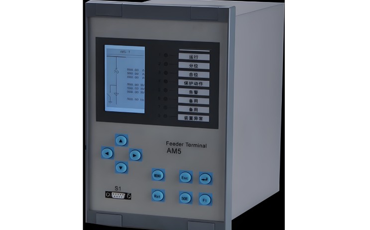
Use a sealed, reinforced enclosure that is resistant to strong vibration and interference, with a compact installation size, suitable for harsh environments and panel mounting.
Use an industrial-grade dual-CPU structure, with each device containing a main CPU and a communication CPU. The two CPUs work in a mutual inspection mode to improve response time and accuracy, prevent maloperation or failure to operate, and enhance stability and reliability.
Full-range temperature automatic compensation allows the device to operate long-term in environments from -20°C to +60°C.
Measurement and protection signals are processed separately within the device, satisfying both accuracy requirements and the requirements for protection range and reliability.
Use a dedicated frequency sampling circuit to precisely track grid frequency, making electrical quantity calculations more accurate.
Use optical isolation for digital input/output, and shielded cables for internal cabinet wiring, effectively preventing external interference and improving the device's anti-interference capability.
Use a large-screen LCD display and soft keypad for clearer numerical display and easier operation.
After commissioning and operation, various protection setting values are stored digitally in EPROM, allowing for immediate recall after commissioning or circuit fault repair.
Equipped with a fully functional circuit breaker operating circuit, suitable for controlling various types of circuit breakers, facilitating substation retrofitting.
Has comprehensive accident analysis capabilities, including protection action event records, electrical quantity signal over-limit records, and fault recording.
4. Role of Microcomputer Integrated Protection Devices in High-Voltage Switchgear
Microcomputer protection devices safeguard against abnormal conditions in circuits. Their roles in high-voltage switchgear include:
Microcomputer protection devices possess powerful data processing, logical computation, and information storage capabilities, featuring advanced internal architectures. They offer complete protection functions equivalent to conventional relay protection. By receiving signals from measurement components such as current and voltage transformers, the device can monitor, control, and protect the circuit state—such as short-circuit protection, overload protection, and single-phase ground fault protection.
Without protection devices, high-voltage switchgear uses relays to achieve these protective functions. Modern microcomputer protection provides enhanced functionality, such as easy remote control, communication with upper-level systems to transmit current, voltage, power, and energy data, and convenient adjustment of protection settings.


