How to select a microcomputer integrated protection device, and what is its function in high-voltage switchgear?

1.Selection and Role of Microcomputer Integrated Protection Devices
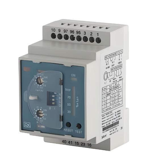
1.1 Selection of Microcomputer Integrated Protection Devices
To ensure a microcomputer integrated protection device correctly and accurately performs its relay protection tasks, selection during design should comprehensively consider reliability, response time, maintenance and commissioning, and additional functions.
Signal input for microcomputer integrated protection devices is the same as traditional relay protection: voltage and current signals are introduced from potential transformers (PTs) and current transformers (CTs), converted by transmitters into standard signals required by the protection device, filtered to remove low- and high-order harmonics and other interference, then converted from analog to digital signals by an A/D converter.
The CPU performs calculations on the digital input, compares the results with preset values, makes judgments, and then decides whether to trigger an alarm or trip. To meet reliability requirements, the measurement and protection input signals are processed and output by independent processing units within the device. This ensures measurement accuracy while providing sufficient margin during severe faults. General engineering reliability is satisfied if the device does not experience A/D overflow or saturation when fault current reaches 20 times the normal value.

1.2 Selection of Response Time
The software workflow of a protection device is generally as shown in the figure below:
It can be seen from the diagram that the response time of a protection device is closely related to the software used and the method of electrical quantity calculation, which is generally unknown to users.
During design and selection, we can only judge the quality of a protection device based on three indicators: calculation accuracy, response time, and computational load. These three factors are mutually conflicting: poor calculation accuracy and small computational load lead to faster response times, while higher accuracy and larger computational load result in slower response. Generally, for end-users of a power grid, setting the computational load to greater than 3 times, calculation accuracy higher than 0.2%, and maximum response time less than 30ms is sufficient to meet typical engineering requirements for response time.
1.3 Selection of Other Functions
Integrated protection devices contain numerous integrated circuits, requiring high-level technical expertise for maintenance. During selection, prioritize devices with modular and standardized hardware, allowing hardware faults to be resolved by simply replacing modules, thus improving work efficiency. Additionally, the protection device should have a built-in EPROM module, enabling all setting values to be stored digitally. Field personnel can then readily recall these settings for equipment commissioning without reprogramming.
To integrate with the overall project automation monitoring system, the protection device should have communication capabilities, enabling easy network formation via data buses and allowing post-trip information to be transmitted to the upper-level automation monitoring system.
2. Relationship between Integrated Protection Devices and Plant-wide Automation Control Systems
Based on the configuration and communication requirements of the plant automation control system, the automation system for microcomputer integrated protection devices is generally divided into three layers: the switchgear layer, substation layer, and central control room.
2.1 Switchgear Layer
The switchgear layer consists of various types of microcomputer integrated protection devices, directly installed on switchgear. Each device directly handles measurement, protection signals, and control functions for its respective cabinet. Specific functions are as follows:
(1) Incoming Line Cabinet
Protection Functions: Instantaneous overcurrent, time-delayed overcurrent.
Measurement Functions: Three-phase current, three-phase voltage, active/reactive power, active/reactive energy.
Monitoring Functions: Circuit breaker open/closed position.
Control Functions: Manual open/close (on cabinet), remote open/close.
Alarm Functions: Trip due to accident, warning signals, open/close status, device fault, fault recording, etc.
(2) Transformer Cabinet
Protection Functions: Instantaneous overcurrent, time-delayed overcurrent, inverse-time overload, single-phase ground fault, heavy gas trip.
Measurement, Monitoring, and Control Functions: Same as incoming line cabinet.
Alarm Functions: Trip due to accident, light gas, temperature alarm, warning signals, open/close status, device fault, fault recording, etc.
(3) Busbar Cabinet
Protection, Monitoring, and Control Functions: Same as incoming line cabinet.
Alarm Functions: Trip due to accident, device fault, fault recording, etc.
(4) Motor Cabinet
Protection Functions: Instantaneous overcurrent, time-delayed overcurrent, overload, single-phase ground, undervoltage, overheating.
Measurement Functions: Three-phase current, three-phase voltage, active/reactive power, active/reactive energy.
Monitoring Functions: Circuit breaker open/closed position.
Control Functions: Manual open/close (on cabinet), remote open/close.
Alarm Functions: Trip due to accident, warning signals, open/close status, device fault, fault recording, etc.
After data acquisition within their respective switchgears, protection devices transmit data via a bus to the monitoring computer at the substation layer. This system greatly reduces control cables, shortens on-site commissioning time, and improves work efficiency.
2.2 Substation Layer
Many signals from the substation need to be transmitted to the central control room via the plant's industrial Ethernet, and control commands from the central control room need to be received and sent to the protection devices. The substation layer typically consists of industrial control computers, printers, and monitors. Its main functions include configuring and managing switchgear protection devices, monitoring system operation, establishing and managing the substation database, and communicating with the central control room.
Due to manufacturers' confidentiality regarding the software and electrical calculation methods of their protection devices, the substation layer must also handle communication protocol conversion to facilitate signal transmission and reception between the central control room and the protection devices.
2.3 Communication Network
Communication between switchgear and the substation can use a MODbus bus network, supporting up to 64 slave stations. Optical isolation is used between the communication network and the devices to prevent external interference. Communication between the substation and the central control room uses an industrial Ethernet with fiber optic media, with a communication rate greater than 1 Mbps.
2.4 Software
System software can use mainstream platforms with international standard architectures, such as Windows NT. Software modules should include: master control software, graphics software, database management software, report generation software, and communication software.
When selecting software, the master control software should have a high degree of modularity. High modularity allows field personnel to call up software based on site conditions without additional programming, significantly reducing the operational and maintenance workload for dispatchers and maintenance staff and improving work efficiency.

3. Other Considerations
Additionally, the following issues should be noted during hardware selection for microcomputer integrated protection devices:
Use a sealed, reinforced enclosure that is resistant to strong vibration and interference, with a compact installation size, suitable for harsh environments and panel mounting.
Use an industrial-grade dual-CPU structure, with each device containing a main CPU and a communication CPU. The two CPUs work in a mutual inspection mode to improve response time and accuracy, prevent maloperation or failure to operate, and enhance stability and reliability.
Full-range temperature automatic compensation allows the device to operate long-term in environments from -20°C to +60°C.
Measurement and protection signals are processed separately within the device, satisfying both accuracy requirements and the requirements for protection range and reliability.
Use a dedicated frequency sampling circuit to precisely track grid frequency, making electrical quantity calculations more accurate.
Use optical isolation for digital input/output, and shielded cables for internal cabinet wiring, effectively preventing external interference and improving the device's anti-interference capability.
Use a large-screen LCD display and soft keypad for clearer numerical display and easier operation.
After commissioning and operation, various protection setting values are stored digitally in EPROM, allowing for immediate recall after commissioning or circuit fault repair.
Equipped with a fully functional circuit breaker operating circuit, suitable for controlling various types of circuit breakers, facilitating substation retrofitting.
Has comprehensive accident analysis capabilities, including protection action event records, electrical quantity signal over-limit records, and fault recording.
4. Role of Microcomputer Integrated Protection Devices in High-Voltage Switchgear
Microcomputer protection devices safeguard against abnormal conditions in circuits. Their roles in high-voltage switchgear include:
Microcomputer protection devices possess powerful data processing, logical computation, and information storage capabilities, featuring advanced internal architectures. They offer complete protection functions equivalent to conventional relay protection. By receiving signals from measurement components such as current and voltage transformers, the device can monitor, control, and protect the circuit state—such as short-circuit protection, overload protection, and single-phase ground fault protection.
Without protection devices, high-voltage switchgear uses relays to achieve these protective functions. Modern microcomputer protection provides enhanced functionality, such as easy remote control, communication with upper-level systems to transmit current, voltage, power, and energy data, and convenient adjustment of protection settings.