1. Fundamentals of Transformer Testing
1.1 Overview
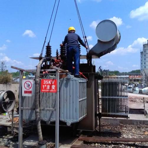
Transformers are among the most critical pieces of equipment for electric power transmission. Their quality and reliability directly affect the safe and dependable delivery of electricity. Damage to generator transformers or key substation transformers can disrupt power transmission, and repairing or transporting such large units often takes several months.
During this downtime, power supply is compromised, adversely impacting industrial and agricultural production as well as residential electricity consumption—resulting in significant economic losses.
As requirements for the safe and reliable operation of transformers continue to rise, transformer testing technologies have advanced considerably over the past two decades. Notable developments include:
Short-circuit tests on large transformers at rated voltage,
Partial discharge measurement and localization techniques,
Application of transfer functions for impulse fault detection,
Use of digital technology for loss measurement,
Introduction of sound intensity methods in noise measurement,
Spectral analysis for diagnosing winding deformation, and
Increasingly widespread use of dissolved gas analysis (DGA) in transformer oil.
1.2 Standards for Transformer Testing
To ensure transformers meet the required standards for power transmission quality and reliability, national standards have been established for both transformers and their testing procedures:
GB 1094.1–1996: Power Transformers – Part 1: General
GB 1094.2–1996: Power Transformers – Part 2: Temperature Rise
GB 1094.3–1985: Power Transformers – Part 3: Insulation Levels, Dielectric Tests and External Clearances in Air
GB 1094.5–1985: Power Transformers – Part 5: Ability to Withstand Short-Circuit
GB 6450–1986: Dry-Type Power Transformers
1.3 Transformer Test Items
1.3.1 Routine Tests
Measurement of winding resistance
Voltage ratio measurement and load loss measurement
Measurement of short-circuit impedance and load loss
Measurement of no-load current and no-load loss
Measurement of insulation resistance between windings and ground
Routine dielectric tests — see Table 1-3 for factory routine insulation test items
On-load tap-changer tests
1.3.2 Type Tests
Temperature rise test.
Insulation type tests (see Table 1).
| Test Item | Test Category |
| External Dielectric Withstand Test | Factory Test |
| Lightning Impulse and Chopped Wave Impulse Test on Line Terminals | Type Test |
| Lightning Impulse Test on Neutral Terminals | Type Test |
| Induced Dielectric Withstand Test | Factory Test |
| Partial Discharge Test | Factory Test |
1.3.3 Special Tests
Measurement of zero-sequence impedance for three-phase transformers.
Short-circuit withstand capability test.
Sound level measurement.
Measurement of harmonic components in no-load current.
2. Voltage Ratio Measurement and Verification of Connection Group Designation
2.1 Overview
Voltage ratio measurement is a routine test for transformers. It is performed not only at the factory during manufacturing but also on-site before the transformer is commissioned into service.
2.1.1 Purpose of Voltage Ratio Measurement
To ensure that the voltage ratios at all tap positions fall within the allowable tolerance specified by standards or contractual technical requirements.
To verify that parallel-connected coils or coil sections (e.g., tapped sections) have identical numbers of turns.
To confirm that tap leads and connections to the tap changer are correctly wired.
Voltage ratio is a critical performance parameter of a transformer. Since this test uses low voltage and is simple to perform, it is conducted multiple times during manufacturing to guarantee compliance with design specifications.
3. DC Resistance Measurement of Windings
3.1 Purpose and Requirements
According to GB 1094.1–1996 “Power Transformers – Part 1: General,” DC resistance measurement is classified as a routine test. Therefore, every transformer must undergo this test both during and after manufacturing.
The primary purposes of measuring DC resistance are to inspect the following aspects:
Quality of welding or mechanical connections between winding conductors—checking for poor joints;
Integrity of connections between leads and bushings, and between leads and the tap changer;
Reliability of welds or mechanical joints between lead wires;
Whether conductor dimensions and resistivity meet specifications;
Balance of resistance among phases;
Calculation of winding temperature rise, which requires measuring cold-state resistance before the temperature rise test and hot-state resistance immediately after power disconnection during the test.
3.2 Measurement Methods
Per JB/T 501–91 “Guide for Power Transformer Testing,” there are two standard methods for measuring DC resistance of transformer windings:
Bridge method (e.g., Kelvin double bridge)
Volt-ampere (V-A) method
4. No-Load Test
4.1 Overview
Measurement of no-load loss and no-load current is a routine transformer test. The complete magnetizing characteristics of a transformer are determined through the no-load test.
The objectives of this test are:
To measure no-load loss and no-load current;
To verify whether the core design and manufacturing process meet applicable standards and technical specifications;
To detect potential core defects, such as localized overheating or insulation weaknesses.
4.2 No-Load Loss
No-load loss primarily consists of hysteresis and eddy current losses in the electrical steel laminations. It also includes additional losses, such as stray losses caused by leakage flux.
4.3 No-Load Current
The magnitude of no-load current is mainly determined by the B–H (magnetization) curve of the electrical steel used in the core.
5. Load Loss and Short-Circuit Impedance Measurement
5.1 Overview of Load Test
Measurement of load loss and short-circuit impedance is a routine test.
Manufacturers perform this test to:
Determine the load loss and short-circuit impedance values;
Verify compliance with standards and technical agreements;
Detect potential defects in windings.
During the test, a voltage is applied to one winding while the other is short-circuited. According to ampere-turn balance, when the current in the energized winding reaches its rated value, the shorted winding also carries rated current.
Although the main magnetic flux in the core is very small during this test, significant leakage flux is generated due to the high current flow. This leakage flux causes:
Eddy current losses in winding conductors;
Circulating current losses in parallel conductors;
Additional losses in clamping structures, tank walls, electromagnetic shields, core frames, and tie plates.
All these losses are current-dependent and are collectively classified as load losses.
6. Applied AC Withstand Voltage Test
6.1 Overview
To ensure transformers are safe and reliable for grid operation, their insulation must meet not only performance standards but also required dielectric strength. Dielectric strength determines whether a transformer can withstand normal operating voltages as well as abnormal conditions such as lightning surges or switching overvoltages.
Only after successfully passing tests—including short-duration power-frequency withstand voltage, impulse withstand voltage, and partial discharge measurements—can a transformer be considered ready for grid connection.
The applied AC withstand test primarily evaluates the main insulation strength between windings and ground, and between windings.
For fully insulated transformers, this test fully validates the main insulation.
For graded-insulation transformers, it only assesses the end-turn insulation near the yoke and the insulation of certain lead sections to ground. It cannot evaluate the full winding-to-ground or inter-winding insulation strength.
For graded-insulation transformers, an induced voltage test is required instead to comprehensively assess insulation strength between windings, to ground, and for associated leads.
7. Induced Overvoltage Withstand Test
7.1 Overview
The induced voltage withstand test is another critical dielectric test following the applied AC test.
For fully insulated transformers, the applied AC test checks only the main insulation, while the turn-to-turn, layer-to-layer, and section-to-section longitudinal insulation is verified by the induced voltage test.
For graded-insulation transformers, the applied AC test only verifies neutral-point insulation. The induced voltage test is essential to evaluate:
Longitudinal insulation (between turns, layers, and sections);
Insulation between windings and ground;
Inter-winding and phase-to-phase insulation.
Thus, the induced voltage test is a vital method for assessing both main and longitudinal insulation integrity.
7.2 Test Requirements
The induced voltage test is typically performed by applying twice the rated voltage to the low-voltage winding terminals, with all other windings left open-circuited. The applied voltage waveform should be as close to a pure sine wave as possible.