Transformer Oil Conservator: Types, Structure, and Functions Explained

Introduction to Transformer Oil Conservator
The oil conservator is a crucial oil storage device for transformers. When the transformer load increases and the oil temperature rises, the insulating oil inside the tank expands due to heat, causing excess oil to flow into the conservator. Conversely, when the temperature decreases, the oil in the conservator flows back into the tank. This process enables automatic oil level regulation, allowing the conservator to serve both oil storage and replenishment functions, ensuring the tank remains fully filled with oil.
At the same time, the conservator reduces the contact area between the transformer oil and air. Moisture, dust, and oxidized oil sludge absorbed from the air settle in the sediment trap at the bottom of the conservator, significantly slowing down the degradation of the transformer oil.
Structure of the Oil Conservator
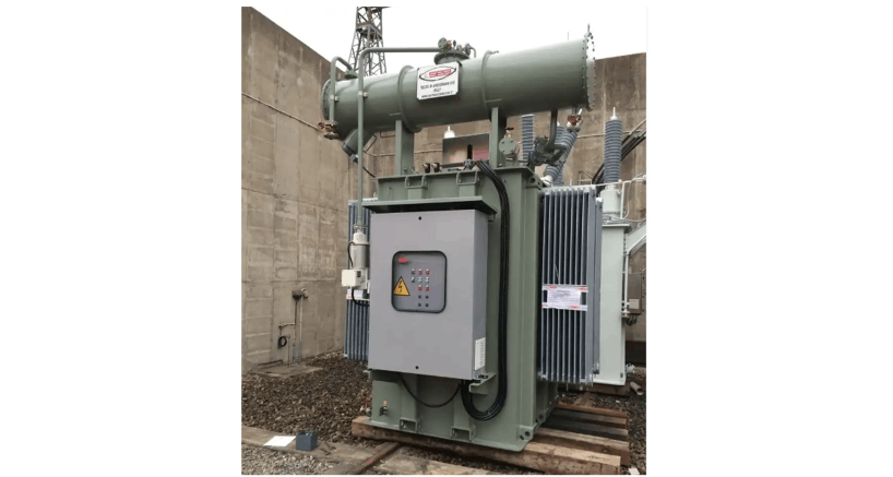
The conservator body is a cylindrical container made of welded steel plates, with a volume approximately 10% of the total tank capacity. It is horizontally mounted on top of the tank and connected to the main tank via a pipeline through a gas relay, allowing the oil level to freely rise and fall with temperature changes. Under normal operating conditions, the minimum oil level in the conservator should be higher than the riser of the high-voltage bushing; for bushings with a connected structure, the minimum oil level should be above the top of the bushing. A glass oil level gauge (or oil level indicator) is installed on the side of the conservator for real-time monitoring of oil level changes.
Types of Oil Conservators
Currently, there are three main types of transformer oil conservators:
Capsule-type conservator: Features a rubber capsule inside that isolates the transformer oil from the external atmosphere while providing space for thermal expansion and contraction.
Diaphragm-type conservator: Uses a rubber diaphragm to separate the oil from air and provides the necessary volume for thermal expansion and contraction.
Corrugated-type conservator: Employs a metal bellows expansion device to isolate the oil from the atmosphere and accommodate changes in oil volume. Corrugated conservators are divided into internal oil and external oil types, with the internal oil type offering better performance but larger size.
Sealing Methods of Oil Conservators
Open-type (non-sealed) conservator: The transformer oil is directly exposed to the external air. This design has poor sealing, making the oil prone to moisture and oxidation, resulting in excessive moisture and gas content, which affects the safe operation of the transformer. This type has been largely phased out and is only found in some low-voltage, small-capacity transformers.
Capsule-type conservator: Equipped with an oil-resistant rubber capsule inside the conservator to isolate the oil from air. The capsule communicates with the atmosphere through a breather pipe and desiccant, expanding and contracting with oil level changes. However, the capsule is susceptible to aging and cracking, allowing moisture and air to enter the oil, leading to oil degradation, reduced insulation performance, and increased dielectric loss. Regular silica gel replacement is required, and severe cases may necessitate oil filtration or power outage maintenance. Its application is gradually decreasing.
Diaphragm-type conservator: Uses a diaphragm structure made of two layers of nylon fabric sandwiched with chloroprene rubber and coated with nitrile rubber on the outside. However, it has high requirements for installation and maintenance processes, with issues such as oil leakage and rubber component damage affecting power supply safety, reliability, and operational cleanliness. Its use is also gradually decreasing.
Metal corrugated (internal oil) sealed conservator: Uses a metal elastic element as a compensator, a mature technology widely used in power systems for over 20 years, extending the technology of plate-type metal expanders used in instrument transformers.
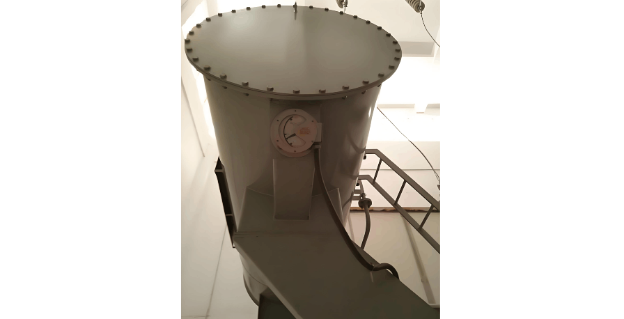
Internal oil vertical conservator: Uses bellows as oil containers, with multiple bellows connected in parallel and vertically installed on a base, an external dust cover added, and oil volume compensation achieved by the vertical movement of the bellows, with a mostly rectangular appearance.
External oil horizontal conservator: Uses bellows as an air bladder, horizontally placed inside the conservator cylinder, with insulating oil filled between the outer side of the bellows and the cylinder, and the inside of the bellows connected to the external air. Oil volume compensation is achieved by the expansion and contraction of the bellows, changing the internal volume of the conservator, with a horizontally placed cylindrical appearance.
Features of Metal Corrugated Oil Conservator
The core cavity is equipped with a damper as a pressure protection device, which can mitigate the impact of sudden increases in internal oil pressure on the conservator body. When the pressure reaches the limit, the core ruptures to release pressure, protecting the transformer body and enhancing operational reliability—a unique feature not found in other conservators.
The core consists of one or more bellows units, with an external protective cover. The outside of the core is exposed to the atmosphere, facilitating good heat dissipation and ventilation, promoting oil circulation, reducing internal oil temperature, and improving operational reliability.
The oil level indicator moves synchronously with the core's expansion and contraction, offering high sensitivity. Oil level changes can be directly observed through a viewing window on the protective cover, providing intuitive and reliable readings. A limit switch for oil level alarm is installed on the protective cover, meeting the requirements for unattended operation.
No false oil level phenomenon: Traditional conservators struggle to completely expel air, potentially causing false oil levels. This design, with its sensitive core movement and a balance steel plate creating slight positive pressure, effectively expels internal air until the desired oil level is reached, eliminating false oil levels.
Metal bellows expanders are not suitable for on-load tap-changer oil tanks: The on-load tap-changer, a key component of the transformer, frequently adjusts voltage based on load conditions during operation. Arcs generated during adjustment lead to oil decomposition and gas production. The limited volume of fully sealed metal bellows expanders hinders gas release, requiring frequent on-site venting. Therefore, manufacturers and users do not recommend using fully sealed metal bellows expanders for small conservators of on-load tap-changers.