• Product
  • Suppliers
  • Manufacturers
  • Solutions
  • Free tools
  • Knowledges
  • Experts
  • Communities
Search


Scott-T Transformer Connection

Edwiin
Field: Power switch
China
Definition: The Scott-T Connection is a technique for linking two single-phase transformers to enable 3-phase to 2-phase conversion and vice versa. The two transformers are electrically connected but operate independently magnetically. One transformer is designated as the main transformer, while the other is termed the auxiliary or teaser transformer.
The diagram below illustrates the Scott-T transformer connection:
  • The main transformer features a center tap at point D and is connected to lines B and C on the 3-phase side. Its primary winding is labeled BC, and its secondary winding is labeled a₁a₂.
  • The teaser transformer is connected between line terminal A and the center tap D. Its primary winding is labeled AD, and its secondary winding is labeled b₁b₂.

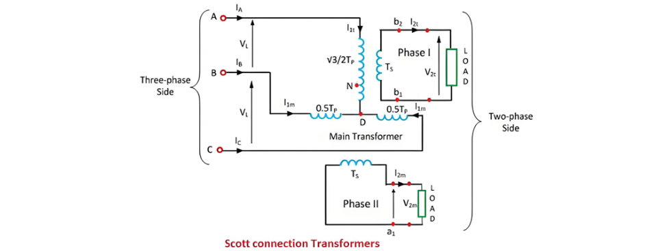
For the Scott-T connection, identical and interchangeable transformers are employed, each featuring a primary winding with Tp turns and equipped with tappings at 0.289Tp, 0.5Tp, and 0.866Tp.
Phasor Diagram of Scott Connection Transformer
The line voltages of the balanced 3-phase system—VAB, VBC, and VCA—are depicted in the figure below, illustrated as a closed equilateral triangle. The diagram also shows the primary windings of the main transformer and the teaser transformer.
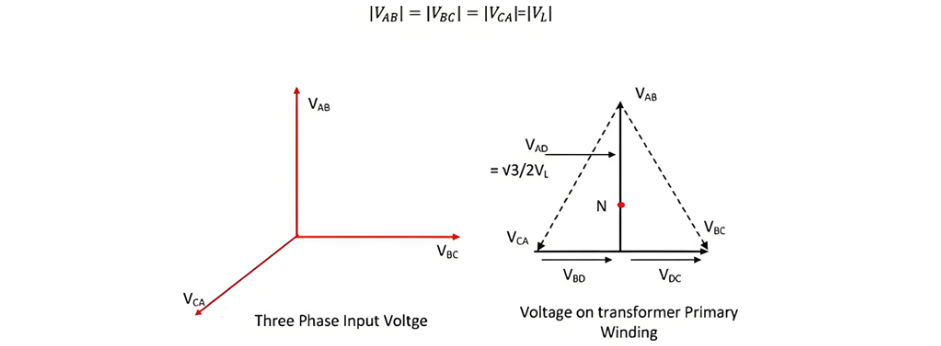
Point D splits the primary winding BC of the main transformer into two equal halves. Consequently, the number of turns in the BD portion equals the number of turns in the DC portion, both being Tp/2. The voltages VBD and VDC are equal in magnitude and in phase with the voltage VBC.
The voltage between A and D is
The teaser transformer has a primary voltage rating of √3/2 (i.e., 0.866) times that of the main transformer. When the voltage VAD is applied to the teaser transformer's primary winding, its secondary voltage V2t leads the main transformer's secondary terminal voltage V2m by 90 degrees, as depicted in the figure below.
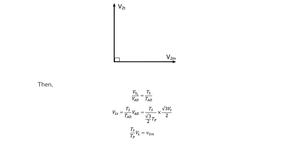
To maintain the same voltage per turn in the primary windings of both the main transformer and the teaser transformer, the number of turns in the teaser transformer's primary must be be √3/2 Tp.
Consequently, the secondaries of both transformers have identical voltage ratings. The secondary voltages V2t and V2m are equal in magnitude but separated by 90º in phase, thereby producing a balanced 2-phase system.
Position of Neutral Point N
The primary windings of the two transformers can form a four-wire connection to a 3-phase supply if a tap N is provided on the teaser transformer's primary such that:
  • The voltage across AN, denoted as VAN), equals the phase voltage, i.e.,VAN= Vt/√3.

The same voltage turn in portion AN, ND and AD are shown by the equations,

The equation above indicates that the neutral point N divides the primary winding of the teaser transformer in the ratio:AN:ND = 2 : 1
Applications of Scott-T Connection
The Scott-T connection finds practical use in the following scenarios:
  • Electric Furnace Installations: It enables the parallel operation of two single-phase furnaces while drawing a balanced load from a three-phase supply, ensuring efficient power distribution and system stability.
  • Single-Phase Load Management: Commonly applied in electrified rail systems (e.g., electric trains), where single-phase loads are scheduled to maintain near-equal loading across all three phases of the supply, minimizing imbalance and optimizing grid performance.
  • Phase Conversion Between Systems: Facilitates bidirectional power flow between three-phase and two-phase systems. While it can convert both ways, practical applications predominantly focus on three-phase to two-phase conversion, as two-phase generators are rarely used in modern power systems.
Give a tip and encourage the author!
Recommended
Ensuring Reliability: A Deep Dive into Transformer Maintenance
IntroductionElectric transformers are the backbone of modern power distribution systems, silently enabling the reliable delivery of electricity to homes, businesses, and industries. As these critical assets age and the demand for uninterrupted power grows, the importance of diligent transformer maintenance has never been greater. This essay explores the essential role of transformer maintenance, highlighting the value of proactive care, the impact of advanced diagnostic technologies, and the tra
Vziman
09/03/2025
How does a transformer work?
Transformer Operation PrincipleA transformer is an electrical device that operates on the principle of electromagnetic induction to transfer electrical energy from one circuit to another. It enables the adjustment of voltage levels within an alternating current (AC) system, either stepping up (increasing) or stepping down (decreasing) voltage while maintaining the same frequency.Working Principle:Basic ComponentsA transformer consists of two coils, known as windings—the "primary winding" connect
Rockwell
09/03/2025
What factors need to be considered when designing a transformer?
Transformer design is a complex process that requires consideration of multiple factors to ensure safe and efficient operation. In addition, compliance with international and local regulations is essential to guarantee that transformers meet safety and performance standards. Below are key factors to consider in transformer design and the relevant regulations to follow:Transformer Design Factors: Voltage and Frequency: Determine the input and output voltage levels and the operating frequency. The
Vziman
09/02/2025
What failure modes are possible in a transformer? How to identify and fix these failures?
Transformers are critical components in power systems, and various failure modes can affect their operation. Timely identification and resolution of these failure modes are essential to prevent costly downtime and ensure system reliability. Below are some common transformer failure modes, along with methods to identify and address them: Insulation FailureIdentification: Insulation failure leads to decreased insulation resistance, which can be detected through insulation resistance testing (megge
Edwiin
09/02/2025
Related Products
  • SYv Series disc - type vacuum on-load tap-changer [OLTC]
  • Photovoltaic inverter grid-connected transformers
  • WDBR-II Transformer capacity tester
  • 75MVA 220kV three-phase gas-insulated transformer(GTI)
Seed Inquiry
Download
Get the IEE Business Application
Use the IEE-Business app to find equipment, obtain solutions, connect with experts, and participate in industry collaboration anytime, anywhere—fully supporting the development of your power projects and business.