Tsamfakar da armature a cikin alternator yana iya zama na tsamfakar da ya faduwa ko na baya. Tsamfakar da ya faduwa tana shirya kungiyoyi na karamin tsamfakar da armature a cikin alternator.
Yana da wasu muhimmanci na duka tsamfakar da armature.
Muhimmancin da ya fi tsamfakar da armature mafi yawan ita ce, labaran wata tsamfaki da za su zama a biyu kan poldo masu nisa. Yana nufin haka, span na tsamfaki = pitch na poli.
Tsamfakar tana iya zama single layer ko double layer.
Tsamfakar ta shirya a wurare da duka slot na armature, domin in yi emf na sinusoidal.
Yana da abubuwa dabam-dabam na tsamfakar da armature da ake amfani a cikin alternator. Tsamfakar tana iya kula da
Tsamfakar da phase na biyu da kuma tsamfakar da phases na uku.
Tsamfakar da ya faduwa da kuma tsamfakar da ya baya.
Tsamfakar da ya haɗu da kuma tsamfakar da ya goma.
Tsamfakar da ya haɗu da kuma tsamfakar da ya biyu.
Lap, wave da tsamfakar da concentric ko spiral da
Tsamfakar da pitch na mafi yawa da kuma tsamfakar da pitch na kadan.
A cikin haka, tsamfakar da armature a cikin alternator tana iya zama integral slot winding da kuma fractional slot winding.
Tsamfakar da phase na biyu a armature tana iya zama concentrated ko distributed type.
An amfani da tsamfakar da ya faduwa idan adadin slots a cikin armature ya zama na musamman da adadin poles a cikin makinta. Wannan tsamfakar da armature a cikin alternator tana bayar da output voltage, amma ba exactly sinusoidal ba.
Tsarin da ya fi tsamfakar da phase na biyu da ya fiye ta shahara a cikin figur-1. A nan, adadin poles = adadin slots = adadin sides na tsamfaki. A nan, side na tsamfaki tana ciki a slot na biyu ta hanyar pole na biyu da side na tsamfaki na biyu tana ciki a slot na uku ta hanyar pole na uku. Emf na iya faruwa a side na tsamfaki tana zama da emf na side na tsamfaki na biyu.

Hakan tsarin da ake shirya tsamfakar a cikin alternator tana nufin skeleton wave winding. Idan kana nemi figur-1, side na tsamfaki-1 ta hanyar N-pole tana kula da side na tsamfaki-2 ta hanyar S-pole a cikin back da side na tsamfaki-3 a cikin front da sauransu.
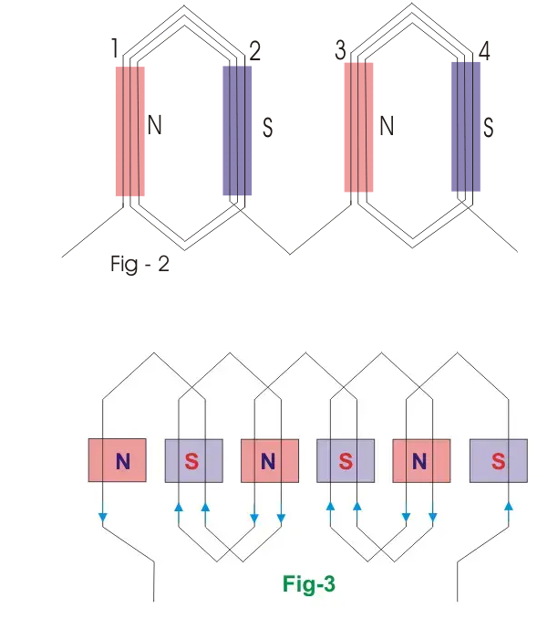
Jihohin emf na iya faruwa a side na tsamfaki-1 tana zuwa hagu da emf na iya faruwa a side na tsamfaki-2 tana zuwa hagu. Saboda haka saboda side na tsamfaki-3 tana ciki a N-pole, tana da emf zuwa hagu da sauransu. Duk da haka, total emf tana shirya da emf na duka sides na tsamfaki. Tsarin da ya fi tsamfakar da armature tana maƙa da lafiya, amma ba ake amfani sosai saboda haka ya bukatar yanayin kyau don kudin end connection na har side ko conductor. Zan iya tabbatar da wannan matsalai, zuwa batu biliyan da multi turns coil. An amfani da multi-turn half coiled winding don samun emf mai yawa. Saboda coils tana ciki a tsari na adadin armature periphery, don haka, muna nufin wannan tsamfakar da hemi-tropic winding. Figur-2 tana nuna hakan. Idan muna kula da duka coils a duk tsari na armature periphery, tsamfakar da armature tana nufin whole coiled winding.
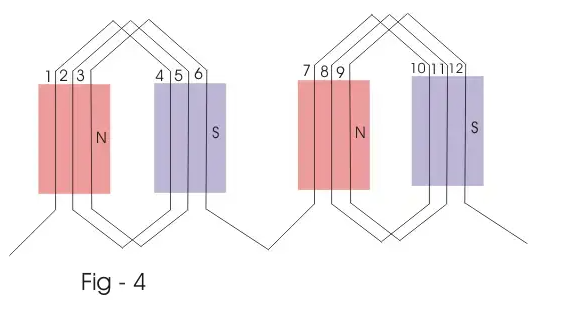
Figur 3 tana nuna double layer winding, inda muna shirya wata side na har tsamfaki a tsari na top na slot na armature, da side na biyu a tsari na bottom na slot. (Tana nuna da dotted lines).

Don samun emf na sinusoidal smooth, conductors tana ciki a slots na biyar ta hanyar pole na biyu. Tsamfakar tana nufin distributed winding. Ba saboda tsamfakar da ya baya a cikin alternator tana rage emf, amma tana maƙa da lafiya saboda:
Tana rage harmonic emf saboda haka waveform tana zama better.
Tana rage armature reaction.
Kula da conductors, tana taimaka waƙoƙi.
Core tana amfani da ita kafin conductors tana ciki a slots a cikin armature periphery.
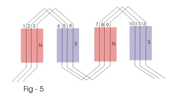
Full pitched lap winding of 4 poles, 12 slots, 12 conductors (one conductor per slot) alternator is shown below.
The back pitch of the winding is equal to the number of conductors per pole, i.e., = 3 and the front pitch is equal to back pitch minus one. The winding is completed per pair of the pole and then connected in series as shown in figure – 4 below.

Wave winding of the same machine, i.e., four poles, 12 slots, 12 conductors is shown in the figure-e below. Here, back pitch and front pitch both equal to some conductor per pole.

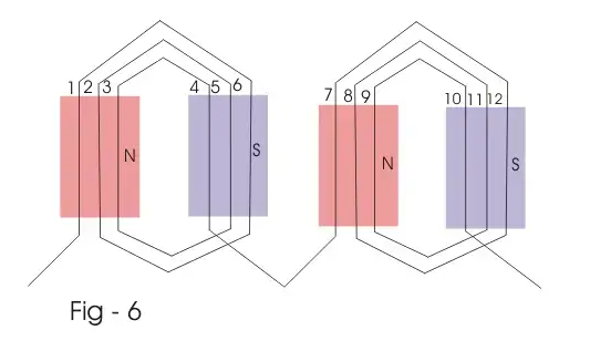
This winding for the same machine, i.e., four poles 12 slots 12 conductors alternator is shown in the figure-f below. In this winding, the coils are of different pitches. The outer coil pitch is 5, the middle coil pitch is 3, and inner coil pitch is one.

Before discussing poly phase armature winding of alternator, we should go through some of the related terms for better understanding.
It is product of number of phases and number of poles in a rotating machine.
Coil group = number of poles × the number of phases.
If under each pole face, there are an equal number of coils of different phases, then the winding is said to be balanced winding. In balanced winding, coil group should be an even number.
If the number of coils per coil group is not a whole number, the winding is known as unbalanced winding. In such case, each pole face contains unequal of coils of different phase. In two-phase alternator, two single-phase windings are placed on the armature by 90 electrical degrees apart from each other.
In case of three phase alternator, three single-phase windings are placed on the armature, by 60 degrees (electrical) apart from each other.
The figure below represents, a Skelton 2 phase 4 pole winding two slots per pole. The electrical phase difference between adjacent slots = 180/2 = 90 degree electrical).
Point a and b are starting point of the first and second phase winding of two, phase alternator. a’ and b’ are finishing point of first and second phase wining of the two-phase alternator, respectively. The figure below represents a Skelton 3 phase 4 pole winding, three slots per pole. The electrical phase difference between, adjacent slots is 180/ 3 = 60 degree (electrical) a, b and c are starting point of Red, Yellow, and blue phases and a’, b’, and c’ are the finishing points of same Red, Yellow and Blue phases of the three-phase winding.
Say red phase winding starts at slot no 1 and ends over slot no 10. Then yellow winding or second winding starts at slot no 2 and ends over slot no 11. Third or blue phase winding starts at slot no 3 and ends at slot no 12. The phase difference of induced emfs, in red phase and yellow, yellow phase and blue phase and blue phase and red phase winding respectively by 60 degrees, 60 degree and 240 degrees (electrical respectively). Since in three phase system, the phase difference between red, yellow and blue phase is 120 degree (electrical). This can be achieved by revering yellow phase (second winding) winding as shown in the figure above.