In UHV GIS, current transformers are key to electric energy metering. Their accuracy determines power trade settlements, so on - site error verification per JJG1021 - 2007 is needed. On - site, use power supplies, voltage regulators, and current boosters. Due to encapsulation in GIS, build test circuits via exposed grounding knives, bushings, and return conductors; right circuits simplify wiring and boost accuracy.
Challenges like large test current, long circuits, and high impedance exist, but reactive compensation (leveraging higher inductive reactance in GIS primary circuits) reduces equipment capacity needs. Accurate primary circuit parameter measurement is key for compensation. Existing methods don’t suit GIS primary circuits, so this paper: sorts UHV GIS current transformer primary circuit structures/features to select verification circuits; develops intelligent methods to enhance parameter measurement intelligence/automation.
1 Primary Circuit Selection for UHV GIS Current Transformers
1.1 Structure & Features
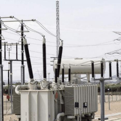
GIS integrates substation primary equipment (excluding transformers) into eight components (e.g., CB, DS). Encapsulated in metal shells, GIS offers: miniaturization (via SF6), less space); high reliability (sealed live parts resist environment/earthquakes); safety (no electric shock/fire risks); superior performance (shields EM/static, no interference); short installation (factory assembly cuts on - site time); easy maintenance & long inspection (good structure, advanced arc extinction).
1.2 Circuit Selection
Circuit breakers sit mid - GIS pipelines, with current transformers on both sides. Disconnectors are outside, plus grounding switches for protection. Pipelines use (SF6), and transformers have epoxy resin semi - casting. Due to enclosure, use exposed grounding switches/bushings + return conductors. Four options exist: grounding switches at breaker ends, GIS pipeline shells, large - current conductors, or adjacent GIS busbars as return. After solving reactive compensation, adjacent GIS busbars (safe, simple, operable) are chosen for on - site verification.
2 Research on GIS Primary Circuit Intelligent Measurement Systems
2.1 Parameter Measurement Method Analysis
GIS primary circuits have equivalent resistance R and inductive reactance (ZL). Conventional methods (measure R, apply AC, calculate complex impedance Z then (ZL) need many devices, complex ops, and heavy calculations. This paper develops intelligent systems. Key tasks: system design (component matching, process planning); determine signal collection (points, methods, circuits for voltage/current); find voltage - current phase difference calculation; select line parameter methods (from amplitude/phase difference, get equivalent resistance/inductive reactance); overcome harmonics/interference for accuracy.
2.2 Overall Design of the Intelligent Measurement System
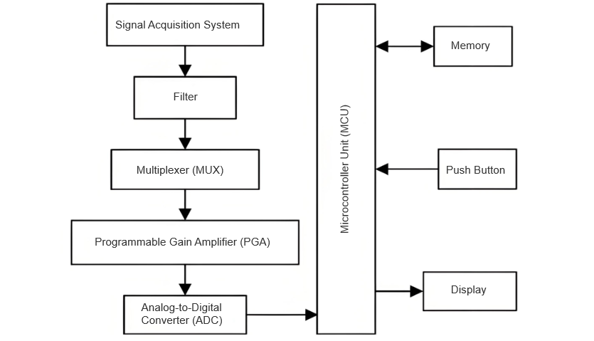
The intelligent measurement system centers around a microcontroller - based computer system, equipped with buttons, a display, a printer, and other peripherals. The voltage and current signals are captured by the signal acquisition system, then processed through a filter, multiplexer switch, automatic signal gain amplifier, and analog - to - digital (A/D) converter before reaching the microcontroller for signal processing. The hardware principle is illustrated in Figure 1.
System Components
Operational Process
The acquired signals are processed and transmitted to the microcontroller, which runs pre - installed signal processing programs. The system analyzes the data via dedicated software, computes the results, and displays them on the screen.
2.3 Design of the Signal Acquisition Circuit
Given that measuring primary circuit parameters doesn’t require high currents, the system uses a regulated power supply with a 200A output. After passing through a current booster, the induced current on the line side is significantly lower than the GIS rated current, minimizing the need for large - capacity equipment. This setup keeps the current within the safe operating range of the GIS enclosure and grounding switches.
Circuit Options
The signal acquisition circuit can adopt any of the three test circuits discussed earlier (excluding the grounding - switch - based circuit, which doesn’t cover the entire GIS line). Using multiple methods simultaneously can enhance measurement accuracy. During testing, voltage and current transformers are installed to convert high primary - side values into manageable secondary - side signals for the acquisition system.
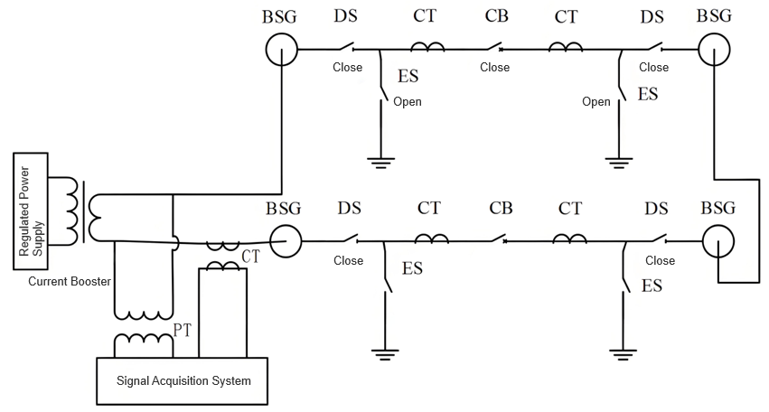
Circuit Design for Adjacent GIS Busbar Return Conductor
When using an adjacent GIS high - current busbar as the return conductor:
The designed signal acquisition circuit is shown in Figure 2. The collected voltage and current data correspond to the total values of the circuit.
2.4 Selection of Calculation Method for Voltage and Current Phase Difference
This measurement system uses the zero - crossing phase angle method to measure the phase difference between voltage and current. The so - called zero - crossing phase angle method is to shape the fundamental wave components of the collected voltage and current signals into square waves, obtain their respective zero - crossing pulses through a differential circuit, measure the time difference between the two pulses, and then calculate the phase difference between the voltage and current.
Assume that the time of the rising edge of the voltage square wave is τ1 and the time of the rising edge of the current square wave is τ2. Then, the calculation formula for the phase difference φ between the two signals is as follows:

Among them: T is the period of voltage and current. Since the frequency of voltage and current is 50 Hz, its period is 0.02 s. The calculation formula for the phase difference of voltage and current can be simplified as:

2.5 Calculation Method for Line Parameters
These calculation processes have been programmed into the microcontroller's memory. Specialized signal - processing software is used to automatically handle the data, and the results are displayed on the device's monitor. For the convenience of analysis, the voltage and current mentioned below are by default considered to have been converted to the voltage and current of the primary side.
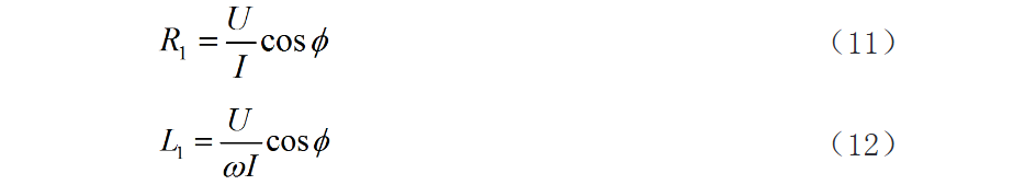
Assume that the amplitude of the total line voltage collected by the signal acquisition system is U, and the amplitude of the line current is I. Then, the total line resistance R1 and inductance L1 can be obtained from the following formulas
If the resistivity of the connecting conductor between the busbars of the GIS outgoing line bushing is measured as ρ, the effective cross - sectional area is s, and the length of the conductor is measured as l, then the impedance calculation formula for this connecting conductor is as follows

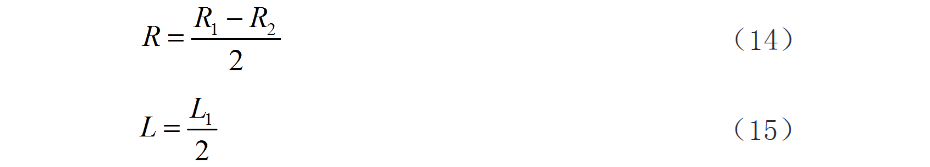
Neglecting other connecting conductors, the equivalent resistance R and equivalent inductance L of the primary circuit of the GIS pipeline can be obtained from the following formulas.
Error Control & Optimization
Each measurement method should be repeated 3 times at different intervals to reduce errors. If feasible, use all 3 methods simultaneously and compare results:
To mitigate interference and harmonics:
3. Conclusion
UHV GIS integrates primary equipment in sealed metal tanks, offering immunity to environmental factors, high reliability, and minimal footprint. For current transformer verification, using adjacent GIS busbars as return conductors simplifies wiring and ensures safety, making it ideal for primary detection circuits.
This study introduces an intelligent measurement system for GIS primary circuits, enabling precise measurement of equivalent resistance and inductance. The system's user - friendly interface, high accuracy, and robust anti - interference capabilities advance automation in GIS verification. Further field testing is recommended for validation and refinement.


 Login
Login