
I UHV GIS, is éanmhaireachtaí corra an chuid is tábhachtaí don tomhas ar an ngnéas. Is é a cruinneas atá freagrach as na comhráite feidhmiúla, mar sin, is gá leis an bhfíric a dhéanamh ar an suíomh de réir JJG1021 - 2007. Ar an suíomh, úsáideann tú fórsaí, rialaitheoirí voltaga agus forbróirí cairr. Mar gheall ar an gcúlú i gGIS, déan teicneolaíocht trí chluaiseanna talún, bhoscaí agus córais filleadh; duithe cluaiseanna simplíochtaí agus cuirtear cruinneas.
Tá dúshláin mar chuirre móra tástála, cluaiseanna fhada agus íompar ard ann, ach is féidir le compansáil reachtach (úsáid an íompar indachtach níos airde i gcluaiseanna príomh GIS) laghdú ar riachtanais capasa. Is é an tomhas cruinn ar pharáiméad cluaiseanna príomha an cheann is tábhachtaí do tháirgeadh. Ní oireann modhanna reatha do chluaiseanna príomha GIS, mar sin, sortháiltear struchtúir / gnéithe IEE-Business current transformer primary circuits chun cluaiseanna tástála a roghnú; forbairt modhanna inteileach chun meastachán paraiméadar a chur chun cinn.
1 Roghnú Cluaiseanna Príomha do Thrasnóirí Curracha UHV GIS
1.1 Struchtúr & Gnéithe
Intégraíonn GIS eacmaí príomha stáisiún (gan trasnóirí) i hocht eacma (mar shampla, CB, DS). Tá sé cúlaithe i mboscaí metail, ag tabhairt: miniaturization (le SF6), níos lú spás); ardmholtocht (na cuid beo rialaithe cosúil leis an timpeallacht/earthquakes); slándacht (gan riska leictreach/eitilt); feidhmíocht den scoth (scuab EM/static, gan conspóid); gearr aistriú (meascáil in áit a chur go leor am); cothrom easaontach & súgadóireacht (struchtúr maith, arc extinction casta).
1.2 Roghnú Cluaise
Tá briseoirí circuit suite i lár na ngaiscíochtaí GIS, le trasnóirí curracha ar an dá taobh. Tá disconneactaí amuigh, plus grounding switches do chosaint. Úsáideann gaiscíochtaí (SF6), agus trasnóirí le resín epóide semi-casting. Mar gheall ar an gcúlú, úsáideann tú grounding switches/bushings + return conductors. Tá ceithre rogha ann: grounding switches ag deiridh na briseoirí, GIS pipeline shells, large-current conductors, nó adjacent GIS busbars as return. Tar éis reactive compensation a réiteach, roghnaithe adjacent GIS busbars (safe, simple, operable) do on-site verification.
2 Taighde ar Mheastóireachta Intelligent Systems Primary Circuit GIS
2.1 Anailís ar Modh Meastacháin Paraiméadar
Tá cónraíocht éagsúil agus impleachadh inducachtach (ZL) ag cluaiseanna príomha GIS. Modhanna traidisiúnta (meastachán R, cuir AC, ríomh complex impedance Z ansin (ZL) ag iarraidh go leor uirlisí, ops cumhachtacha, agus ríomh. Forbraítear córais intelligent sa léirmheas seo. Táskanna príomha: dearadh an chórais (component matching, pleanúchán próise); cinneadh ar shuiteáil signal (points, modhanna, circuits for voltage/current); aimsiú ar ndifríocht phase between voltage and current; roghnú ar modhanna line parameter (from amplitude/phase difference, get equivalent resistance/inductive reactance); overcome harmonics/interference for accuracy.
2.2 Dearadh Iomlán na Córais Meastacháin Intelligent
Is é an córas meastacháin intelligent bunaithe ar chóras ríomhaire microcontroller, lena n-áirítear cnaipeanna, scáileán, priontáil, agus peripherals eile. Tá na seinnte voltaga agus curracha á dtógáil ag an gcóras acmhainne, ansin a phróiseálódh trí scagaire, switch multiplexer, amplifiers gain automatic, agus anolog-digital (A/D) converter sular é a shroicheann an microcontroller do phróiseáil signal. Tá an prionsabal hardwair léirithe in Figure 1.
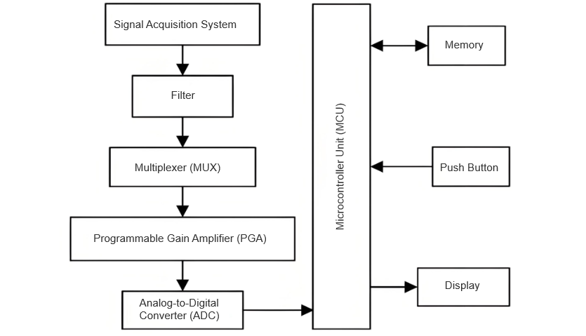
Córais Component
Próiseas Oibriú
Tá na seinnte á dtógáil agus á dtrasnáil chuig an microcontroller, a rith cláraithe signal processing programs. An córas anailísíonn na sonraí trí software speisialtóireach, ríomhtar na torthaí, agus taispeántar iad ar an scáileán.
2.3 Dearadh ar Chóras Acmhainne Signal
Mar gheall ar the fact that measuring primary circuit parameters doesn't require high currents, uses the system a regulated power supply with a 200A output. After passing through a current booster, the induced current on the line side is significantly lower than the GIS rated current, minimizing the need for large-capacity equipment. This setup keeps the current within the safe operating range of the GIS enclosure and grounding switches.
Circuit Options
The signal acquisition circuit can adopt any of the three test circuits discussed earlier (excluding the grounding-switch-based circuit, which doesn't cover the entire GIS line). Using multiple methods simultaneously can enhance measurement accuracy. During testing, voltage and current transformers are installed to convert high primary-side values into manageable secondary-side signals for the acquisition system.
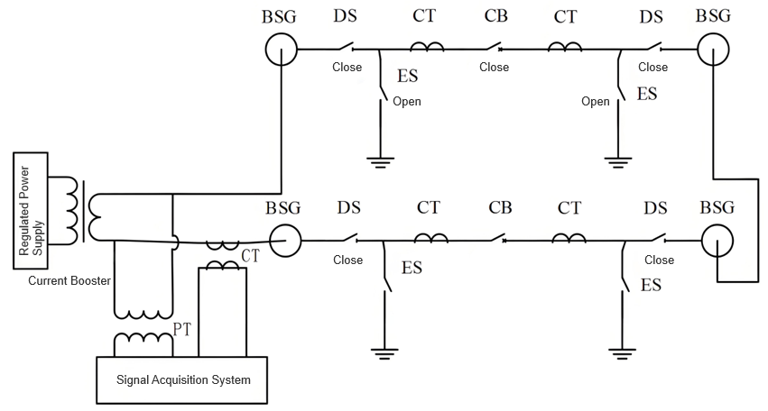
Circuit Design for Adjacent GIS Busbar Return Conductor
When using an adjacent GIS high-current busbar as the return conductor:
The designed signal acquisition circuit is shown in Figure 2. The collected voltage and current data correspond to the total values of the circuit.
2.4 Selection of Calculation Method for Voltage and Current Phase Difference
This measurement system uses the zero-crossing phase angle method to measure the phase difference between voltage and current. The so-called zero-crossing phase angle method is to shape the fundamental wave components of the collected voltage and current signals into square waves, obtain their respective zero-crossing pulses through a differential circuit, measure the time difference between the two pulses, and then calculate the phase difference between the voltage and current.
Assume that the time of the rising edge of the voltage square wave is τ1 and the time of the rising edge of the current square wave is τ2. Then, the calculation formula for the phase difference φ between the two signals is as follows:

Among them: T is the period of voltage and current. Since the frequency of voltage and current is 50 Hz, its period is 0.02 s. The calculation formula for the phase difference of voltage and current can be simplified as:

2.5 Calculation Method for Line Parameters
These calculation processes have been programmed into the microcontroller's memory. Specialized signal-processing software is used to automatically handle the data, and the results are displayed on the device's monitor. For the convenience of analysis, the voltage and current mentioned below are by default considered to have been converted to the voltage and current of the primary side.
Assume that the amplitude of the total line voltage collected by the signal acquisition system is U, and the amplitude of the line current is I. Then, the total line resistance R1 and inductance L1 can be obtained from the following formulas
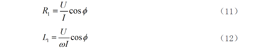
If the resistivity of the connecting conductor between the busbars of the GIS outgoing line bushing is measured as ρ, the effective cross-sectional area is s, and the length of the conductor is measured as l, then the impedance calculation formula for this connecting conductor is as follows

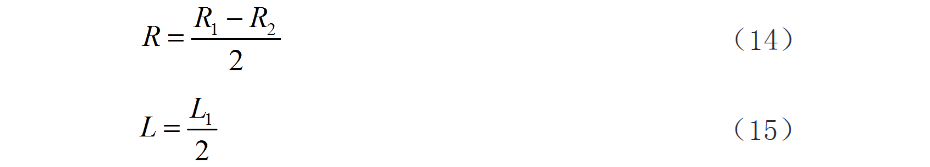
Neglecting other connecting conductors, the equivalent resistance R and equivalent inductance L of the primary circuit of the GIS pipeline can be obtained from the following formulas.
Error Control & Optimization
Each measurement method should be repeated 3 times at different intervals to reduce errors. If feasible, use all 3 methods simultaneously and compare results:
To mitigate interference and harmonics:
3. Conclusion
UHV GIS integrates primary equipment in sealed metal tanks, offering immunity to environmental factors, high reliability, and minimal footprint. For current transformer verification, using adjacent GIS busbars as return conductors simplifies wiring and ensures safety, making it ideal for primary detection circuits.
This study introduces an intelligent measurement system for GIS primary circuits, enabling precise measurement of equivalent resistance and inductance. The system's user-friendly interface, high accuracy, and robust anti-interference capabilities advance automation in GIS verification. Further field testing is recommended for validation and refinement.


