What are the possible causes of cracking failure in CT terminal blocks within GIS equipment?

Gas - insulated switchgear (GIS) , often called “SF6 combined electrical apparatus”, is widely used in power systems for its high reliability, small footprint, low noise, and low loss. It encloses high - voltage devices like circuit breakers, fast grounding switches, current transformers, and busbars in a grounded metal shell filled with SF6 gas . Each device sits in a separate gas chamber with different pressures. The CT terminal block divides gas chambers, connects components, and eases maintenance . A converter station found a 750kV GIS CT gas chamber’s pressure dropped ~0.05MPa daily, persisting after gas refilling. Thus, we analyzed the CT terminal block’s failure.
1 Overview and Cracking Analysis of the Terminal Block
1.1 Overview
Put into operation on 2017 - 06 - 23, the terminal block leaked gas on 2021 - 11 - 06 and showed cracks on 2021 - 11 - 08. The flat side is CT - side, convex is non - CT - side, with 12 outer threaded holes. CT - side has three circles of equidistant yellow copper terminal posts (1, 8, 15 per circle from inside); non - CT - side’s outermost circle has 15 posts (A1 - A5, B1 - B5, C1 - C5 counterclockwise), matching CT - side in middle circles.
1.2 Macroscopic Inspection
A ~30cm - long crack was found on the convex side, at the raised edge’s turn, split into two sections: a wide - opened long crack (A1 - B1) and a small - opened short crack (C5 - A1, barely visible). Penetrant testing followed to check for more cracks.
1.3 Penetrant Testing
Penetrant testing was conducted on both sides of the terminal block:
Convex side: Two cracks were found, consistent with macroscopic inspection in morphology and length (240mm and 60mm). The short crack became obvious after testing, and no other cracks were detected.
Flat side: Two cracks of different lengths (approximately 20mm and 8mm) were found at the inner sealing ring. They did not penetrate through, with an end - to - end distance of about 20mm.
1.4 Fracture Surface Inspection
A section cut from A4 showed non - CT - side penetrative cracks and CT - side non - penetrative ones. Square conductive sheets and hexagonal nuts inside had structural abrupt changes,with penetrant back - seepage (gaps between metal inserts and epoxy resin). Fine cracks (30° to the terminal block axis) and uneven, spotted contact surfaces (with 45° - angled cracks) were seen.
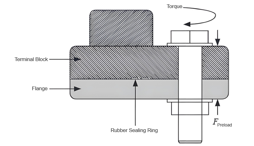
1.5 Force Calculation
With the manufacturer’s 25Nm bolt torque, using T = kFd ((k = 0.15), the single - bolt vertical preload was 13.9kN. Simulating max preload (M12 bolt, 50cm torque wrench) gave 220Nm torque (44Nm via a 10cm - arm wrench), raising preload to 24.4kN (1.76× standard). The 30° - angled, 31.78mm - long fracture had a 10.78mm discontinuous joint (resin stress increase). Excessive preload and stress concentration caused crack initiation and propagation in resin.
2 Causes of Cracking
Excessive bending stress on the discontinuous seat structure (edge bolt hole - terminal post) caused penetrative cracks. Improper tools/over - tightening led to excessive bolt preload. CT - side gas pressure
added to bending stress. Poor metal - resin bonding (gaps) reduced bearing cross - section and caused stress concentration. Combined, these cracked the terminal block, leaking gas.
3 Preventive Measures
Use torque wrenches per manufacturer specs to avoid over - tightening. Follow gas - filling processes to prevent pressure differences. Optimize terminal block design/casting to avoid stress - causing gaps/sharp inserts. Strengthen quality checks to reject faulty products.
4 Conclusion
CT terminal block cracking in SF6 apparatus resulted from improper bolt - tightening (excessive preload). The proposed measures guide other power users.


